This thread has been locked.
If you have a related question, please click the "Ask a related question" button in the top right corner. The newly created question will be automatically linked to this question.
Tool/software: TI C/C++ Compiler
Hi everyone,
I have work on a project with communications.
There are two chip on the PCB, and they are MSP430F2122(I2C master) and MSP430F5632(I2C slave)
The operation of the project is,
2122 transmit UART data to chip1 -> 2122 receive UART data from chip1 ->2122 transmit UART data to chip2 -> ...(polling to all chips of the project) -> 2122 read and write I2C data to 5632 ->2122 transmit UART data to chip1 -> 2122 receive UART data from chip1 ->...(repeat)
After the whole system is reset, each operations seems normal.
UART can run in a correct way that is same as my setting and never miss data under communicating.
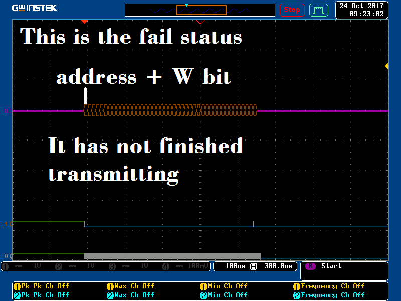
But when the 2122 run I2C communication for several times, 2122 keeps being reset.(When I2C stuck, I clear WTDCTL to reset 2122)
How can I solve the problem of the I2C communication error?
I guess there are something wrong in 2122 or 5632, but I don't know why.
The protocol is below,
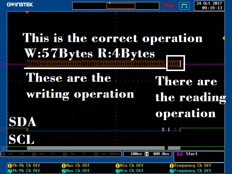
Frequency for I2C operation : about 100KHz
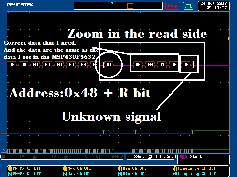
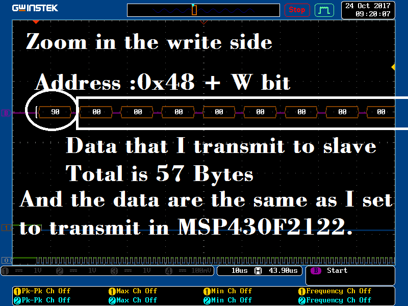
Address of 5633(I2C slave) : 0x48
Number of data to 5633 : 57 bytes
Number of data from 5633 : 4 bytes
And the code is below,
2122:
void I2C_Multiple_Read_Write(unsigned char Length,unsigned short number_of_read)
{
unsigned int i;
unsigned short loop;
_DINT();
while (UCB0STAT & UCBUSY); // wait until I2C module has
// finished all operations
//Transmit
UCB0CTL1 |= UCTR; // UCTR=1 => Transmit Mode
IFG2 &= ~UCB0TXIFG;// disable Receive ready interrupt
IE2 &= ~UCB0RXIE;// enable Transmit ready interrupt
IE2 |= UCB0TXIE;
UCB0CTL1|= UCTXSTT; // send start condition
while(UCB0CTL1 & UCTXSTT) // Ensure start condition got sent
{
if(!(UCNACKIFG & UCB0STAT)) // Break out if ACK received
break;
}
for(loop=0;loop<Length;loop++)
{
while (!(IFG2 & UCB0TXIFG)); // check if UCB0TXBUF=empty
UCB0TXBUF = I2C_data[loop];
i=0;
while (!(IFG2 & UCB0TXIFG))
{
//if i2c hang on, ignore I2C data
i++;
if (i==9999)
//break;
WDTCTL =0;//reset
}
}
//while (!(UCB0IFG & UCTXIFG)); // check if UCB0TXBUF=empty
//Receive
UCB0CTL1 &= ~UCTR; // UCTR=0 => Receive Mode
IFG2 &= ~UCB0RXIFG;
IE2 &= ~UCB0TXIE; // disable Transmit ready interrupt
IE2 |= UCB0RXIE; // enable Receive ready interrupt
UCB0CTL1 |= UCTXSTT; // send start condition
i=0;
while(UCB0CTL1 & UCTXSTT) // Ensure start condition got sent
{
if(!(UCNACKIFG & UCB0STAT)) // Break out if ACK received
break;
}
for(loop=0;loop<number_of_read;loop++)
{
while (!(UCB0RXIFG & IFG2)); //recive data
UART_data[loop]=UCB0RXBUF;
}
UCB0CTL1 |= UCTXSTP; // send stop condition
while(UCB0CTL1 & UCTXSTP); // Ensure stop condition got sent
__no_operation();
UCB0CTL1 |= UCSWRST;
UCB0CTL1 &= ~UCSWRST;
_EINT();
}
5632:
#pragma vector = USCI_B1_VECTOR
__interrupt void USCI_B1_ISR(void)
{
switch(__even_in_range(UCB1IV,12))
{
case 0:// Vector 0: No interrupts
break;
case 2:// Vector 2: ALIFG
break;
case 4:// Vector 4: NACKIFG
break;
case 6:// Vector 6: STTIFG
UCB1IFG &= ~UCSTTIFG;
break;
case 8:// Vector 8: STPIFG
UCB1IFG &= ~UCSTPIFG;
if((I2C_Stat & 0x40)==0x40)
{
I2C_Stat=0;
UCB1IE &= ~UCTXIE;//Disable TX interrupt of I2C
}
break;
case 10:// Vector 10: RXIFG
I2C_data[(I2C_Stat&0x3F)] = UCB1RXBUF;// Get RXD byte into buffer
I2C_Stat++;
if((I2C_Stat&0x3F)>56)
{
I2C_Stat|=0x80;
}
break;
case 12:// Vector 12: TXIFG
UCB1TXBUF = I2C_data[I2C_TX_loop++];
break;
default:
break;
}
}
Sincerely,
Norton
Hi Norton,
This is the MSP430F2122 that is resetting, correct?
First, I recommend you read through the general and I2C section of the Solutions to Common eUSCI and USCI Serial Communication Issues on MSP430 MCUs application report. Next can you probe the I2C bus with a scope or logic analyzer to record the transactions taking place. Then can you post these screenshots to the forum for me to review. Finally, can you provide code for the I2C setup being used in the MSP430F2122?
Best regards,
Caleb Overbay
Hi Ryan and Caleb,
With the advice from Ryan, I changed some part of my I2C communication code.
But if I do not check whether the buffer of TXD is empty or not, the data to transmit will not successful.
Now, I cancel the reset part of the I2C communication.
I will paste the code below, void I2C_Multiple_Read_Write(unsigned char Length,unsigned short number_of_read)
As the following figures, they are the screenshot from Oscilloscope.
And I have write the meanings on the figures.
Each time the fail operation occurs, it happens in the part of transmitting.
I have not finished transmitted the data and it stuck, so I think the error is in the chip MSP430F5632 which my slave device of I2C right?
As the following codes are,
Master part,
1. I2C setting operation in MSP430F2122(Master), check with InitI2C(unsigned char i2c_address).
2. I2C communication of MSP430F2122(Master), check with I2C_Multiple_Read_Write(void).
Slave part,
3. I2C setting operation in MSP430F5632(Slave), check with Set_I2C_Slave(void).
4. I2C USCI_B0 interrupt service routine in MSP430F5632(Slave), check with __interrupt void USCI_B1_ISR(void)
After finishing receiving, I do an operation for data assignment then enable the TXIE to send back data.
5. check with I2C_RX_data_operation(void)
void InitI2C(unsigned char i2c_address) { //i2c_address should shift for a bit, because address of I2C assign to buffer ignore last bit //use RXD mode to send start condition this bit is set to Hi //use TXD mode to send start condition this bit is set to Lo //EX: i2c_address define as 0x50(01010000) actually assign address is 0xA0(10100000), //but the LSB is decided by RXD mode or TXD mode //Recommended initialisation steps of I2C module as shown in User Guide: UCB0CTL1 |= UCSWRST; // Enable SW reset UCB0CTL0 = UCMST + UCMODE_3 + UCSYNC; // I2C Master, synchronous mode UCB0CTL1 = UCSSEL_2 + UCSWRST; // Use SMCLK, TX mode, keep SW reset UCB0BR0 = 0x12; // fSCL = SMCLK/12 = ~100kHz UCB0BR1 = 0x00; UCB0I2CSA = i2c_address; // define Slave Address // In this case the Slave Address // defines the control byte that is // sent to the EEPROM. UCB0I2COA = 0x48; // own address. UCB0CTL1 &= ~UCSWRST; // Clear SW reset, resume operation if (UCB0STAT & UCBBUSY) // test if bus to be free { // otherwise a manual Clock on is generated P3SEL &= ~SCL; // Select Port function for SCL P3OUT &= ~SCL; P3DIR |= SCL; // drive SCL low P3SEL |= SDA + SCL; // select module function for the used I2C pins } } void I2C_Multiple_Read_Write(unsigned char Length,unsigned short number_of_read) { unsigned int i; unsigned short loop; _DINT(); while (UCB0STAT & UCBUSY); // wait until I2C module has // finished all operations //Transmit UCB0CTL1 |= UCTR; // UCTR=1 => Transmit Mode IFG2 &= ~UCB0TXIFG;// disable Receive ready interrupt IE2 &= ~UCB0RXIE;// enable Transmit ready interrupt IE2 |= UCB0TXIE; UCB0CTL1|= UCTXSTT; // send start condition while(UCB0CTL1 & UCTXSTT) // Ensure start condition got sent { if(!(UCNACKIFG & UCB0STAT)) // Break out if ACK received break; } for(loop=0;loop<Length;loop++) { while (!(IFG2 & UCB0TXIFG)); // check if UCB0TXBUF=empty UCB0TXBUF = I2C_data[loop]; i=0; //while (!(IFG2 & UCB0TXIFG)) //{ //if i2c hang on, ignore I2C data //i++; //if (i==9999) //break; //WDTCTL =0;//reset //} } while (!(IFG2 & UCB0TXIFG)); // check if UCB0TXBUF=empty //Receive UCB0CTL1 &= ~UCTR; // UCTR=0 => Receive Mode IFG2 &= ~UCB0RXIFG; IE2 &= ~UCB0TXIE; // disable Transmit ready interrupt IE2 |= UCB0RXIE; // enable Receive ready interrupt UCB0CTL1 |= UCTXSTT; // send start condition i=0; while(UCB0CTL1 & UCTXSTT) // Ensure start condition got sent { if(!(UCNACKIFG & UCB0STAT)) // Break out if ACK received break; } for(loop=0;loop<number_of_read;loop++) { while (!(UCB0RXIFG & IFG2)); //recive data I2C_data[loop]=UCB0RXBUF; } UCB0CTL1 |= UCTXSTP; // send stop condition while(UCB0CTL1 & UCTXSTP); // Ensure stop condition got sent __no_operation(); UCB0CTL1 |= UCSWRST; UCB0CTL1 &= ~UCSWRST; _EINT(); } void Set_I2C_Slave(void) { UCB1CTL1 |= UCSWRST; // Enable SW reset UCB1CTL0 = UCMODE_3 + UCSYNC; // I2C Slave, synchronous mode UCB1I2COA = 0x48; // Own Address is 048h UCB1CTL1 &= ~UCSWRST; // Clear SW reset, resume operation UCB1IE |= UCSTPIE + UCSTTIE + UCRXIE;// + UCTXIE;// Enable STT, STP & RX, TX interrupt } //********************************* //* I2C Interrupt Service Routine * //********************************* #pragma vector = USCI_B1_VECTOR __interrupt void USCI_B1_ISR(void) { switch(__even_in_range(UCB1IV,12)) { case 0:// Vector 0: No interrupts break; case 2:// Vector 2: ALIFG break; case 4:// Vector 4: NACKIFG break; case 6:// Vector 6: STTIFG UCB1IFG &= ~UCSTTIFG; break; case 8:// Vector 8: STPIFG UCB1IFG &= ~UCSTPIFG; if((I2C_Stat & 0x40)==0x40) { I2C_Stat=0; UCB1IE &= ~UCTXIE;//Disable TX interrupt of I2C } break; case 10:// Vector 10: RXIFG I2C_data[(I2C_Stat&0x3F)] = UCB1RXBUF;// Get RXD byte into buffer I2C_Stat++; if((I2C_Stat&0x3F)>56) { I2C_Stat|=0x80; } break; case 12:// Vector 12: TXIFG UCB1TXBUF = I2C_data[I2C_TX_loop++]; break; default: break; } } void I2C_RX_data_operation(void) { /* I2C data communication, X is transmit variables I2C_data array Up_Light[5]; 0 1 2 3 4 Dn_Light[5]; 5 6 7 8 9 FLR_Light[5]; 10 11 12 13 14 Stat[3]; X 15 X FLR_Dir; X Total_FLR; 16 Connect_Stat; 17 Car_OP[2]; 18 19 Dir_Operation; X Spec[5]; 20 21 22 23 24 FLR_BTN[5]; 25 26 27 28 29 Up_BTN[5]; 30 31 32 33 34 Dn_BTN[5]; 35 36 37 38 39 Dis_FLR_BTN[5]; 40 41 42 43 44 Dis_Up_BTN[5]; 45 46 47 48 49 Dis_Dn_BTN[5]; 50 51 52 53 54 Car_IP[2]; 55 56*/ unsigned char loop; if((I2C_Stat&0x80)==0x80) { //*************************** //* Receive From I2C Master * //*************************** for(loop=0;loop<5;loop++) { Up_Light[loop]=I2C_data[loop];//0~4 Dn_Light[loop]=I2C_data[(loop+5)];//5~9 FLR_Light[loop]=I2C_data[(loop+10)];//10~14 Spec[loop]=I2C_data[(loop+20)];//20~24 FLR_BTN[loop]=I2C_data[(loop+25)];//25~29 Up_BTN[loop]=I2C_data[(loop+30)];//30~34 Dn_BTN[loop]=I2C_data[(loop+35)];//35~39 Dis_FLR_BTN[loop]=I2C_data[(loop+40)];//40~44 Dis_Up_BTN[loop]=I2C_data[(loop+45)];//45~49 Dis_Dn_BTN[loop]=I2C_data[(loop+50)];//50~54 } Stat[1]=I2C_data[15]; Total_FLR=I2C_data[16]; Connect_Stat=I2C_data[17]; Car_OP[0]=I2C_data[18]; Car_OP[1]=I2C_data[19]; Car_IP[0]=I2C_data[55]; Car_IP[1]=I2C_data[56]; //*************************** //* Send back to I2C Master * //*************************** I2C_data[0]=Stat[0]; I2C_data[1]=Stat[2]; I2C_data[2]=FLR_Dir; I2C_data[3]=Dir_Operation; I2C_Stat=0x40;//TX mode I2C_TX_loop=0; UCB1IE |= UCTXIE;//Enable TX interrupt of I2C } }
Hi Ryan,
Thanks for your kind advice. Maybe I should check my communication code.
Correctly, I do not send back an ACK/NACK in the slave part.
I did not see any operations for a ACK/NACK in the sample code.
Maybe I check with the wrong sample.
I will check with other sample code again and make a correction with my code.
After that, I will paste and tell you the solution.
If there is any suggestions or solutions, please let me know.
Sincerely,
Norton
**Attention** This is a public forum