This thread has been locked.

If you have a related question, please click the "Ask a related question" button in the top right corner. The newly created question will be automatically linked to this question.

MSP430F437: Sleep Mode Issue

Part Number: MSP430F437
Other Parts Discussed in Thread: MSP-FET

Please pardon my ignorance with regards to device operation and application. I am new to this project and my first task is to resolve a recent manufacturing issue. While I'm bringing myself up to speed on our own development, application, code, etc., I would like to simply state the issue to see if anyone has experienced a similar problem.

We have a board with a separate processor Vcc and a system Vcc. We shut the device down through detection of a button press on an attached keypad. Once detected, we have a small delay, disable the system Vcc, and place the processor into sleep mode (powered by the processor Vcc). Our most recent production is experiencing a 20% failure as the processor will not shut down or is immediately waking back up.

  • Nothing has changed in our manufacturing process.
  • The design has not changed.
  • The firmware has not changed.
  • The power switch control line is clean with no noise issues.

We are solving the problem by replacing the processor with a part pulled from our engineering box of loose components. While the components share an identical part number, the component has a different manufacturing code indicated on the component.

Failing part: 68CNCKTG4

Working part: 56APHVTG4

We contacted our authorized supplier and they are not aware of a problem with this product. I'm assuming that the supplier also verified chain of custody of the parts to make sure we are not dealing with a counterfeit component issue. They simply recommended that I call the tech support number which then sent me here.

Any help would be appreciated.

  • Hi,

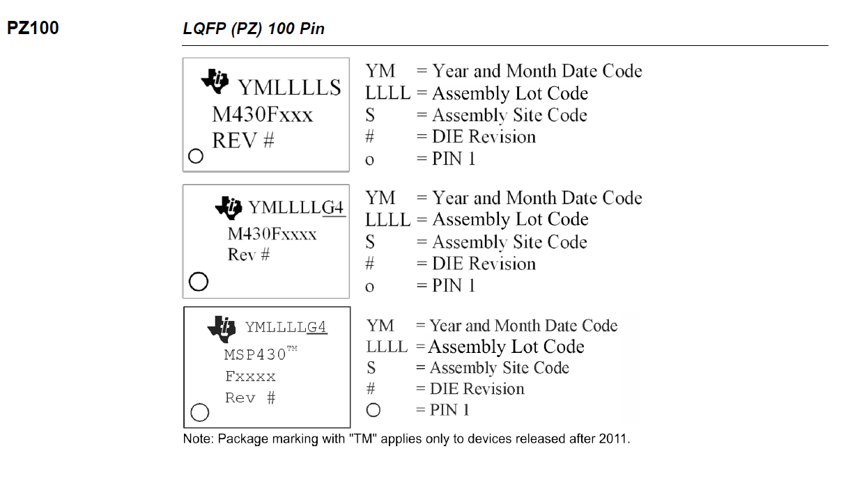
    can you please check the revision of the MSP430F437? The revsion # can be found directly on the package:

     You may also want to check the device errata sheet. The errata sheet lists the known issues of the device together with workarounds. 

    http://www.ti.com/lit/slaz208

    Best regards,

    Andre

  • 56APHVTG4 Rev H
    68CNCKTG4 Rev H
    75ATH3TG4 Rev H

    Further inspection determined that the current production run used a mixture of parts manufactured at two different times. Our tower is down so I have no way of determining if the components came from two different reels or the same reel. Our current reel has 28 components left on it, all manufactured in 2017.

    The failure rates provided to me by production were for the complete production testing to date. A count of the boards tested to date indicates that approximately 40% of the boards tested used the 2016 component and 60% tested used the component from 2017. Given that there was a 20% failure rate of all units and all units that failed used the component from 2016, I can deduce that the failure rate of components from 2016 is currently at 50%.

    Is there a way to find out if the manufacturing code (68CNCKTG4) is valid for the given part?
  • Hi,

    as all devices have the same revision, I have some further questions.
    1. Can you provide a basic block diagram showing the basic building blocks as well as the system VCC and processor VCC?
    2. What LPM's are you using?
    3. How do you put the MSP430F437 into sleep, and how do you wake it up?
    4. Are unused pin's configured correctly? Please check chapter 2.5 "Connection of Unused Pins" of the User's Guide: http://www.ti.com/lit/slau056. Especially look at IO ports
    5. Have you checked the system VCC and processor VCC on a scope for unexpected spikes or drops?

    Best regards,
    Andre
  • Sorry for the delayed response and thanks again for your help. As mentioned in my original post, I'm new to this project but I'm also new to the MSP430.

    1. Simple switching regulator on battery powers the processor. Processor enables/disables power to the rest of the board through a diode current switch.
    2. We are using lower power mode 4.
    3. Processor runs in NMI mode when in use. Long press on NMI pin causes shutdown. When shut down is determined, the devices switches everything off and waits on port pin to go high, returns to reset mode, then goes to low power mode 4. Reset is then used to wake the instrument up.

    We have a very (VERY) slow reset line. Apparently a large resistor was used to reduce current consumption. I can hold the instrument NMI/RST pin low and let everything shut down. As long as I hold the pin low, everything is off. Once the NMI/RST line is released, the pin comes up slowly and the MSP430 either resets immediately and never makes it to sleep mode or the pin triggers the reset once the MSP430 is placed in reset mode. My MSP-FET is on order so I can't trace the problem internally just yet.

    What I have found, I reduced the size of the reset resistor and the problem goes away.

    So have we been pushing the limits of the reset line?

    Is there a minimum ΔV/Δt requirement that must be met on the reset line?
  • Got my MSP-FET. Found the following:

    void Shutdown(void)
    {
    do {
    asm("nop");
    } while ((P1IN & 0x01) == 0);
    
    [do stuff here]
    
    WDTCTL = WDTPW + WDTHOLD;
    
    [DEVICE RESETS]
    
    ...
    }

    So the device resets before it can be placed in sleep mode. It appears that despite monitoring a pin that is also tied to the reset line, the reset line is seen as still being low while the pin is seen as being high. A simple delay before the WDTCTL command gave the reset line enough time to recover and the device would no longer reset. This is also why decreasing the pull-up resistor on the reset line had the same effect.

    Best explanation: the newer micros reacted differently from previous micros with regards to the state of the reset line due to our pushing the limits of the pull-up resistor.

    I'll flag this problem as being solved.

**Attention** This is a public forum