This thread has been locked.
If you have a related question, please click the "Ask a related question" button in the top right corner. The newly created question will be automatically linked to this question.
Hello,
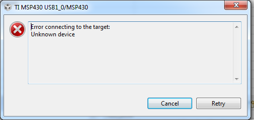
I am trying to debug the port pin toggling program to MSP430FR2110 with using MSP-FETFlash Emulation tool. firstly i have connected this controller to FET using 4 wire connection as suggested in hardware tool with eternal power supply on pin no 4 of FET .i have checked JTAG connections connectivity twice . But when i tried to debug fresh controller using CCS V7 i have got error specifying that "Error Connecting to the target: Unknown device". then i have tried with various combinations after checking every time JTAG connection are following
1) i have tried with various capacitor on Reset pin 10nF,47pF and 1nF with Fixed resistor as 47Kohms
2) tried with 2 wire debugging specified for MSP430FR series (NC to Test pin of FET tht is 8 No pin) with external power and FET power.
3)Tried with power up controller from FET(from 2nd no pin)
4) changing USB port of computor
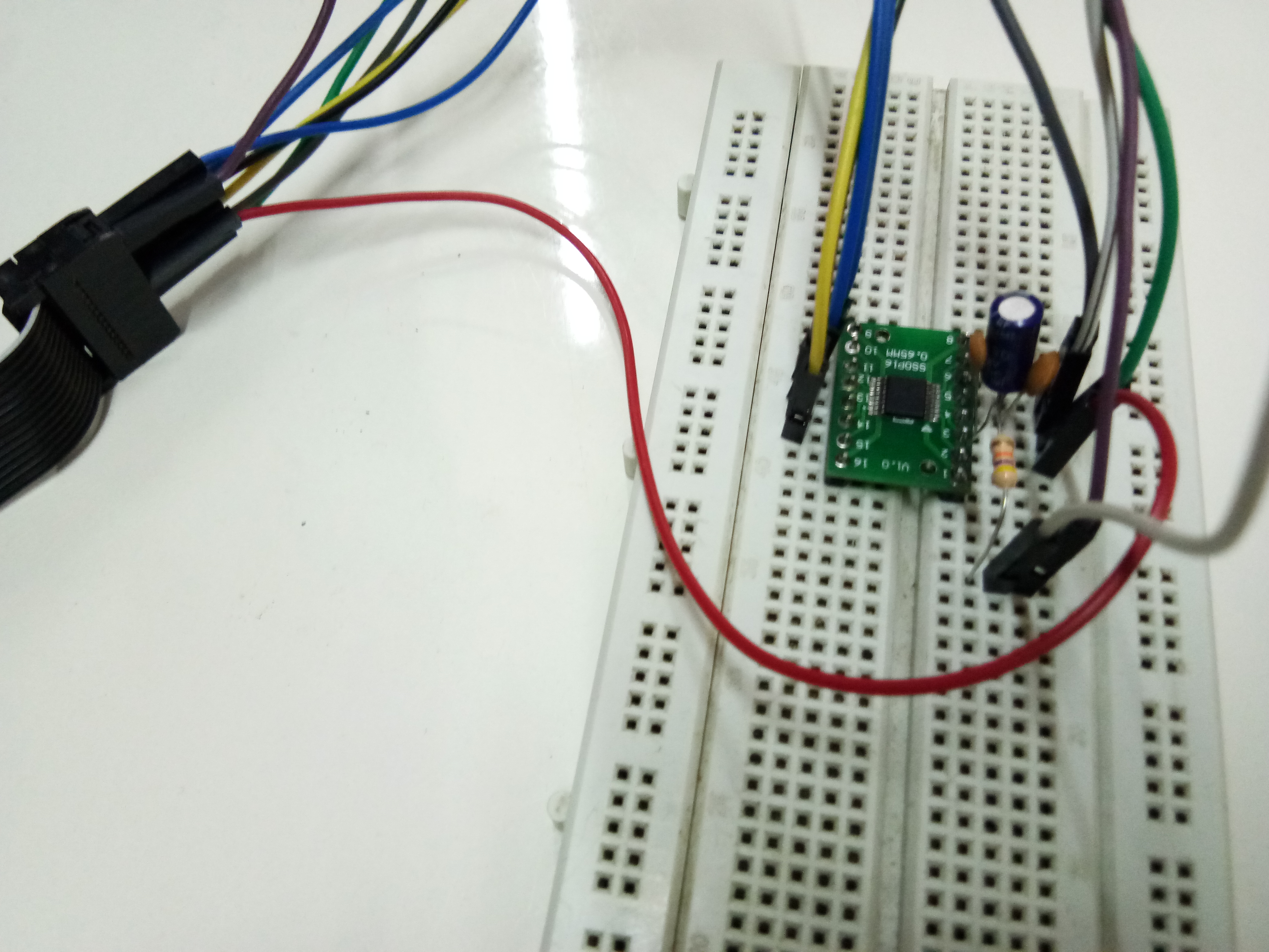
5)Tried with soldering controller on breakout board and tested on Breadboard
6) tried debug my controllers using of Emulator(eZ-FET V1.2) of MSP430FR4133 launchpad
7) also tried on CCS V6.2
8) updating CCS and FET
when i am trying to use 2 wire connection on MSP430FR4133 launch pad using external FET its work fine only with FET power mode not in external power mode, as i saw in launchpad circuit it have 47K with 1nF on RST pin trying with same value on MSP430FR2110 its showing same error . also MSP43FR4133 will not working on 4 wire mode.
I have tried on another MSP430FR4133 own designed board its worked only once for 2 wire mode and 4 wire mod with FET power but when i am tried 2nd time its not working showing same error.
now the condition is i can not debug MSP430FR2110 Nor MSP430FR4133(my own board).
Please suggest how to proceed? also i will tried to find out solutions from my side.
i have not connected any component other than decoupling capacitor between DVCC an DVSS
Hello Dennis,
thank you for your response.
actually this schematic diagram is correct but problem is with symbol used in the schematic. In circuit i have used 4 pin push button which have 1 and 2 pin are internally shorted and 3 and 4 pin are internally shorted. when button is pushed all pin are connected and when open 1 and 2 are isolated from 3 and 4 pin. for 2 pin push button you can assume 1 pin is (1 and 2 shorted together for 4 pin button ) and 2 pin is (3 and 4 are shorted together of 4 pin connector) .
reset switch which is used in my schematic as 1 and 2 pin are shorted so pull resistor and capacitor will automatically appear and RST pin of micro controller as well as JATG connector.
and when button is press RST pin connected to ground.
Hello Dennis Lehman,
I am giving power to MSP430FR4133 form MSP FETFlash emulation tool and i have checked on pin using DMM is 3.33V. Also i am sharing RST pin snapshot from DSO. i am putting DSO on single shot and pressing debug button of CCS and this wave form are appears and gain i am putting on single shot and pressing Run button on CCS (green arrow) then nothing is appear on DSO.
Currently my controller is ( PCB of MSP430FR4133 ) is working fine.i have tried 3-4 time debug to controller its working. before while facing this problem with MSP430FR4133 PCB i have tried Spy-Bi-Wire mode once its work and after i have tried 4 wire JTAG. but its gives problem on JTAG debugging. but after 2-3 hour its work. after this que. posted while searching and reading i got some information that Spy-Bi-Wire will unstable the internal crystal. after that i haven't tried on Spy-Bi-Wire and working with only 4 pin JTAG with MSP FET and its working.
Dear Dennis Lehman,
yes, MSP430FR4133 board are working with only 4-wire JTAG for (i have not tried spy-by-wire mode after board working with 4 wire JTAG). i have not changed in any thing in circuit only thing is i have power off board around 2 hours after this problem occur and then tried with JTAG.
but condition is now is MSP430FR4133 is working fine with 4 wire JTAG mode and still MSP430FR2110 is not working any more.
2 nd image in above reply is RST in of MSP430FR2110. and its still giving error while debug.
sorry, i am finding that document where read about spy-by-wire and unstable crystal. i will paste it when i got it.
Hi Dennis Lehman ,
after reading your reply i had checked my board again my borad layout and itf correct.
But still not trusting on board i am working on breackout board( which contain only controller) and breadbord. Connections are follow
JATG pin configuration FR2110 configuration
TDO (1) TDO(11)
TDI (3) TDI(12)
TMS (5) TMS(13)
TCK(7) TCK(14)
GND(9) DVSS(6)
RST(11) RST(4)
TEST(8) TEST(3)
VCC_Tool(2) DVCC(5)
DVCC have 2 parallel capacitor of 1uF (electrolyte) and 0.1uF of (ceramic) wit respect to DVSS
and pull up resistor of 47K ohms(one terminal to 3.3V and another to RST pin) and connected to 1nF capacitor(one terminal to RST pin and another to GNG)(common point between resistor and capacitor is shorted to RST oF JATG and FR2110(JTAG RST-->common node of res-cap-->FR2110 RST))
with this configration i have debug the controller after last switching of RST pin shown in waveform the pop up window is appear on CCS screen showing Error Connecting to the target: Unknown device massage on window
i ahve tried with same configation by changing power setting instead of giving power from MSP flash tool i have power device and MSP flash tool( at pin 4) from external power supply. In the overall testing the power is constant 3.3VDC (from MSP Flash tool ( 3.33V)
i am attaching the image of setup and waveform of RST pin appeared on DSO
**Attention** This is a public forum