- Ask a related questionWhat is a related question?A related question is a question created from another question. When the related question is created, it will be automatically linked to the original question.
Part Number: MSP432P401R
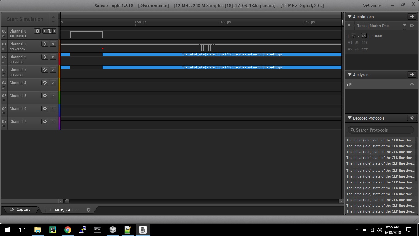
I am uploading my MSP432 code with which I am expecting to communicate to ADS1292(A board from proto-central is being used for the purpose) schematic is pc_ads1292r_brk_v3.pdf
I have tried my best in writing the code where I try to enable SPI, UART one by one with the help of SDK of MSP432 provided by TI, glad that it has helped me in writing fastly
but I find the problem in accessing the registers of AD1292 over SPI through MSP432, every time i read the board through SPI in debug mode each step takes lot of dealy than required
Here is my complete code bundle in the form of 6175.project.zip,
if you face any file not found during compilation , its due to include path , you have open Build>variables and change the MSP lib path to the where msp lib headers are present, or one has to download them if not there
Let me show the code flow
important decalrations / pins to which UART and SPI are connected
* Use with SPI Slave Data Echo code example.
 *
 *                MSP432P401
 *              -----------------
 *             |                 |
 *             |                 |
 *             |                 |
 *             |             P1.6|-> Data Out (UCB0SIMO)
 *             |                 |
 *             |             P1.7|<- Data In (UCB0SOMI)
 *             |                 |
 *             |             P1.5|-> Serial Clock Out (UCB0CLK)
 * Author: Timothy Logan
*******************************************************************************/

#define  ADS1292_DRDY_PORT  GPIO_PORT_P2
#define  ADS1292_DRDY_PIN   GPIO_PIN3 //J4.34
#define  ADS1292_CS_PORT    GPIO_PORT_P5
#define  ADS1292_CS_PIN     GPIO_PIN1 //J4.33
#define  ADS1292_START_PORT GPIO_PORT_P3
#define  ADS1292_START_PIN  GPIO_PIN5 //J4.32
#define  ADS1292_PWDN_PORT  GPIO_PORT_P3
#define  ADS1292_PWDN_PIN   GPIO_PIN7 //J4.31

/* SPI Master Configuration Parameter */
const eUSCI_SPI_MasterConfig spiMasterConfig =
{
        EUSCI_B_SPI_CLOCKSOURCE_SMCLK,             // SMCLK Clock Source
        //3000000,                                   // SMCLK = DCO = 3MHZ
        1000000,                                   // SMCLK = DCO = 1MHZ
        500000,                                    // SPICLK = 500khz
        EUSCI_B_SPI_MSB_FIRST,                     // MSB First
        EUSCI_B_SPI_PHASE_DATA_CHANGED_ONFIRST_CAPTURED_ON_NEXT,    // Phase
        EUSCI_B_SPI_CLOCKPOLARITY_INACTIVITY_HIGH, // High polarity
        EUSCI_B_SPI_3PIN                           // 3Wire SPI Mode
};

/* UART Configuration Parameter. These are the configuration parameters to
 * make the eUSCI A UART module to operate with a 115200 baud rate. These
 * values were calculated using the online calculator that TI provides
 * at:
 * software-dl.ti.com/.../index.html
 */
const eUSCI_UART_Config uartConfig =
{
        EUSCI_A_UART_CLOCKSOURCE_SMCLK,          // SMCLK Clock Source
        13,                                      // BRDIV = 13
        0,                                       // UCxBRF = 0
        37,                                      // UCxBRS = 37
        EUSCI_A_UART_NO_PARITY,                  // No Parity
        EUSCI_A_UART_MSB_FIRST,                  // MSB First
        EUSCI_A_UART_ONE_STOP_BIT,               // One stop bit
        EUSCI_A_UART_MODE,                       // UART mode
        EUSCI_A_UART_OVERSAMPLING_BAUDRATE_GENERATION  // Oversampling
};
please note these are code snippets only full code is present with project uploaded
Initialization part
int Setup_Initialization()
{

        /* Halting WDT  */
       WDT_A_holdTimer();

       /* Initialize the  data ready and chip select pins*/
       GPIO_setAsInputPin(ADS1292_DRDY_PORT,ADS1292_DRDY_PIN);
       GPIO_setAsOutputPin(ADS1292_CS_PORT,ADS1292_CS_PIN);
       GPIO_setAsOutputPin(ADS1292_START_PORT,ADS1292_START_PIN);
       GPIO_setAsOutputPin(ADS1292_PWDN_PORT,ADS1292_PWDN_PIN);

       /* Selecting P1.5 P1.6 and P1.7 in SPI mode */
       GPIO_setAsPeripheralModuleFunctionInputPin(GPIO_PORT_P1,
               GPIO_PIN5 | GPIO_PIN6 | GPIO_PIN7, GPIO_PRIMARY_MODULE_FUNCTION);

       /* Configuring SPI in 3wire master mode */
       SPI_initMaster(EUSCI_B0_BASE, &spiMasterConfig);

       /* Enable SPI module */
       SPI_enableModule(EUSCI_B0_BASE);

       /* Enabling interrupts */
       SPI_enableInterrupt(EUSCI_B0_BASE, EUSCI_B_SPI_RECEIVE_INTERRUPT);
       Interrupt_enableInterrupt(INT_EUSCIB0);
       Interrupt_enableSleepOnIsrExit();

       /* Selecting P1.2 and P1.3 in UART mode and P1.0 as output (LED) */
       GPIO_setAsPeripheralModuleFunctionInputPin(GPIO_PORT_P1,
                GPIO_PIN2 | GPIO_PIN3, GPIO_PRIMARY_MODULE_FUNCTION);
       GPIO_setAsOutputPin(GPIO_PORT_P1, GPIO_PIN0);
       GPIO_setOutputLowOnPin(GPIO_PORT_P1, GPIO_PIN0);

       /* Setting DCO to 24MHz (upping Vcore) */
       FlashCtl_setWaitState(FLASH_BANK0, 2);
       FlashCtl_setWaitState(FLASH_BANK1, 2);
       PCM_setCoreVoltageLevel(PCM_VCORE1);
       CS_setDCOCenteredFrequency(CS_DCO_FREQUENCY_24);

       /* Configuring UART Module */
       UART_initModule(EUSCI_A0_BASE, &uartConfig);

       /* Enable UART module */
       UART_enableModule(EUSCI_A0_BASE);

       /* Enabling interrupts */
       UART_enableInterrupt(EUSCI_A0_BASE, EUSCI_A_UART_RECEIVE_INTERRUPT);
       Interrupt_enableInterrupt(INT_EUSCIA0);
       Interrupt_enableSleepOnIsrExit();

       /*ADS 1292 Initialization*/
       /*ADS1292 Reset*/
       GPIO_setOutputHighOnPin(ADS1292_PWDN_PORT, ADS1292_PWDN_PIN);
       delay(100);                 // Wait 100 mSec
       GPIO_setOutputLowOnPin(ADS1292_PWDN_PORT, ADS1292_PWDN_PIN);
       delay(100);
       GPIO_setOutputHighOnPin(ADS1292_PWDN_PORT, ADS1292_PWDN_PIN);
       delay(100);
       /*Disable Start*/
       GPIO_setOutputLowOnPin(ADS1292_START_PORT,ADS1292_START_PIN);
       delay(20);
       /*Enable Start*/
       GPIO_setOutputHighOnPin(ADS1292_START_PORT,ADS1292_START_PIN);
       delay(20);
       /*Hard Stop*/
       GPIO_setOutputLowOnPin(ADS1292_START_PORT,ADS1292_START_PIN);
       delay(100);
       /*Send Command Data START*/
       ads1292_SPI_Command_Data(START);
       /*Soft Stop*/
       ads1292_SPI_Command_Data(STOP);
       delay(50);
       /*Stop read data continuous*/
       ads1292_SPI_Command_Data(SDATAC);
       delay(300);

       ads1292_Reg_Write(ADS1292_REG_CONFIG1, 0x00);        //Set sampling rate to 125 SPS
       delay(10);
       ads1292_Reg_Write(ADS1292_REG_CONFIG2, 0b10100000);   //Lead-off comp off, test signal disabled
       delay(10);
       ads1292_Reg_Write(ADS1292_REG_LOFF, 0b00010000);      //Lead-off defaults
       delay(10);
       ads1292_Reg_Write(ADS1292_REG_CH1SET, 0b01000000);    //Ch 1 enabled, gain 6, connected to electrode in
       delay(10);
       ads1292_Reg_Write(ADS1292_REG_CH2SET, 0b01100000);    //Ch 2 enabled, gain 6, connected to electrode in
       delay(10);
       ads1292_Reg_Write(ADS1292_REG_RLDSENS, 0b00101100);   //RLD settings: fmod/16, RLD enabled, RLD inputs from Ch2 only
       delay(10);
       ads1292_Reg_Write(ADS1292_REG_LOFFSENS, 0x00);        //LOFF settings: all disabled
       delay(10);
                                                               //Skip register 8, LOFF Settings default
       ads1292_Reg_Write(ADS1292_REG_RESP1, 0b11110010);     //Respiration: MOD/DEMOD turned only, phase 0
       delay(10);
       ads1292_Reg_Write(ADS1292_REG_RESP2, 0b00000011);     //Respiration: Calib OFF, respiration freq defaults
       delay(10);
       /*Stop read data continuous*/
       ads1292_SPI_Command_Data(RDATAC);
       delay(10);

       /*Enable Start*/
       GPIO_setOutputHighOnPin(ADS1292_START_PORT,ADS1292_START_PIN);
       delay(20);
return 0;
}
communication with ADS1292
void ads1292_SPI_Command_Data(uint8_t command)
{

   TXData  =  command;
   GPIO_setOutputLowOnPin(ADS1292_CS_PORT, ADS1292_CS_PIN);
   delay(2);
   GPIO_setOutputHighOnPin(ADS1292_CS_PORT, ADS1292_CS_PIN);
   delay(2);
   GPIO_setOutputLowOnPin(ADS1292_CS_PORT,ADS1292_CS_PIN);
   delay(2);
   /* Polling to see if the TX buffer is ready */
    while (!(SPI_getInterruptStatus(EUSCI_B0_BASE,EUSCI_B_SPI_TRANSMIT_INTERRUPT)));

   /* Transmitting data to slave */
   SPI_transmitData(EUSCI_B0_BASE, TXData);

   GPIO_setOutputHighOnPin(ADS1292_CS_PORT, ADS1292_CS_PIN);
   delay(2);

}
void ads1292_Reg_Write(uint8_t READ_WRITE_ADDRESS,uint8_t DATA)
{
uint8_t dataToSend;
switch (READ_WRITE_ADDRESS)
  {
    case 1:
            DATA = DATA & (uint8_t)0x87;
        break;
    case 2:
            DATA = DATA & (uint8_t)0xFB;
        DATA |= 0x80;
        break;
    case 3:
        DATA = DATA & (uint8_t)0xFD;
        DATA |= 0x10;
        break;
    case 7:
        DATA = DATA & (uint8_t)0x3F;
        break;
    case 8:
            DATA = DATA & (uint8_t)0x5F;
        break;
    case 9:
        DATA |= 0x02;
        break;
    case 10:
        DATA = DATA & 0x87;
        DATA |= 0x01;
        break;
    case 11:
        DATA = DATA & 0x0F;
        break;
    default:
        break;
  }

  // now combine the register address and the command into one byte:
  dataToSend = READ_WRITE_ADDRESS | WREG;

  GPIO_setOutputLowOnPin(ADS1292_CS_PORT, ADS1292_CS_PIN);
  delay(2);
  GPIO_setOutputHighOnPin(ADS1292_CS_PORT, ADS1292_CS_PIN);
  delay(2);
  GPIO_setOutputLowOnPin(ADS1292_CS_PORT,ADS1292_CS_PIN);
  delay(2);

  /*Send Register Location*/
  /* Polling to see if the TX buffer is ready */
  while (!(SPI_getInterruptStatus(EUSCI_B0_BASE,EUSCI_B_SPI_TRANSMIT_INTERRUPT)));
  /* Transmitting data to slave */
  SPI_transmitData(EUSCI_B0_BASE, dataToSend);

  /*Number of Register to Write*/
  /* Polling to see if the TX buffer is ready */
  while (!(SPI_getInterruptStatus(EUSCI_B0_BASE,EUSCI_B_SPI_TRANSMIT_INTERRUPT)));
  /* Transmitting data to slave */
  SPI_transmitData(EUSCI_B0_BASE, 0x00);

  /*Number of Register to Write*/
  /* Polling to see if the TX buffer is ready */
  while (!(SPI_getInterruptStatus(EUSCI_B0_BASE,EUSCI_B_SPI_TRANSMIT_INTERRUPT)));
  /* Transmitting data to slave */
  SPI_transmitData(EUSCI_B0_BASE, DATA);
  delay(2);
  GPIO_setOutputHighOnPin(ADS1292_CS_PORT, ADS1292_CS_PIN);
  delay(2);
}
most important and problematic code is this
void delay( const int msec)
{
    volatile int i;
    for( i=0;i<msec;i++);
   // __delay_cycles(msec);
}
main loop to send recieved data over UART
int main(void)
{
    int i, j;
    Setup_Initialization();
    while(1)
    {
        if (ads1292dataReceived == true)
        {
            j=0;
            for(i=0;i<6;i+=3)                  // data outputs is (24 status bits + 24 bits Respiration data +  24 bits ECG data)
            {

                uecgtemp = (unsigned long) (  ((unsigned long)SPI_RX_Buff[i+3] << 16) | ( (unsigned long) SPI_RX_Buff[i+4] << 8) |  (unsigned long) SPI_RX_Buff[i+5]);
                uecgtemp = (unsigned long) (uecgtemp << 8);
                secgtemp = (signed long) (uecgtemp);
                secgtemp = (signed long) (secgtemp >> 8);

                s32DaqVals[j++]=secgtemp;
            }

            DataPacketHeader[0] = CES_CMDIF_PKT_START_1 ;   // Packet header1 :0x0A
            DataPacketHeader[1] = CES_CMDIF_PKT_START_2;    // Packet header2 :0xFA
            DataPacketHeader[2] = (uint8_t) (data_len);     // data length
            DataPacketHeader[3] = (uint8_t) (data_len>>8);
            DataPacketHeader[4] = CES_CMDIF_TYPE_DATA;      // packet type: 0x02 -data 0x01 -commmand

            DataPacketHeader[5] = s32DaqVals[1];            // 4 bytes ECG data
            DataPacketHeader[6] = s32DaqVals[1]>>8;
            DataPacketHeader[7] = s32DaqVals[1]>>16;
            DataPacketHeader[8] = s32DaqVals[1]>>24;

            DataPacketHeader[9] = s32DaqVals[0];            // 4 bytes Respiration data
            DataPacketHeader[10] = s32DaqVals[0]>>8;
            DataPacketHeader[11] = s32DaqVals[0]>>16;
            DataPacketHeader[12] = s32DaqVals[0]>>24;

            DataPacketHeader[13] = CES_CMDIF_TYPE_DATA;   // Packet footer1:0x00
            DataPacketHeader[14] = CES_CMDIF_PKT_STOP ;   // Packet footer2:0x0B

            for(i=0; i<15; i++){
                UART_transmitData(EUSCI_A0_BASE, DataPacketHeader[i]);     // transmit the data over USB
            }
            ads1292dataReceived = false;
            SPI_RX_Buff_Count = 0;
        }
    }

//    PCM_gotoLPM0();
//    __no_operation();
}
SPI Interrupt Handler
//******************************************************************************
//
//This is the EUSCI_B0 interrupt vector service routine.
//
//******************************************************************************
void EUSCIB0_IRQHandler(void)
{
    uint32_t status = SPI_getEnabledInterruptStatus(EUSCI_B0_BASE);
    volatile uint32_t jj;

    SPI_clearInterruptFlag(EUSCI_B0_BASE, status);

    if(status & EUSCI_B_SPI_RECEIVE_INTERRUPT)
    {

        RXData = SPI_receiveData(EUSCI_B0_BASE);

        SPI_RX_Buff[SPI_RX_Buff_Count++] = RXData;  // store the result data in array

        if (SPI_RX_Buff_Count > 8){
            SPI_RX_Buff_Count = 0;
            ads1292dataReceived = true;
        }

        /* Delay between transmissions for slave to process information */
        for(jj=0;jj<50;jj++);

    }
}


**Attention** This is a public forum