


Other Parts Discussed in Thread: ADS8353
Tool/software: Code Composer Studio
SBAS584BGood Afternoon,
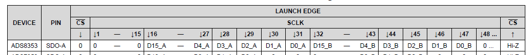
I am currently attempting to use an MSP430FR4133 to speak with an ADS8353 for 16-bit resolution using SPI. There is a confusing issue. The data being sent by the ADS8353 is absolutely correct and matches with the datasheet. Annoyingly, it sends 15 bits in response to a command, then 16-bit channel 1 data, 16-bit channel 2 data then an obligatory 0 for a total of 48 bits aka one frame. (p.41 SBAS584B Table 14: Launch Data Edge).
This exactly matches what we are seeing on an oscilloscope.
There are two strange things happening.
- The most important, the MSB for Channel 1 is lost. We receive a 0 for it independent of its actual value, then 15 meaningful bits. Then we receive 16 meaningful bits for Channel 2, and lastly the tail 0 as mentioned in the table above. It's being sent but the MSP isn't recognizing it.
- The values being read are one cycle behind. If you send, and then read then we are getting the data that should have been an 8-bit cycle ago.
#include <msp430.h>
#include <string.h>
#include <stdio.h>
#include <driverlib.h>
void SYSTEMinit();
int writeUART(char* sentence);
void sendZeros (int NumberOfTimes);
int main(void)
{
char buffer[50];
SYSTEMinit();
uint16_t value[8];
int j;
while(1)
{
P5OUT &=~ BIT0; //Turns ADC on
while ((UCB0IFG & UCTXIFG) == 0);
UCB0TXBUF = 0x00;
while ((UCB0IFG & UCRXIFG) == 0);
value[0] = UCB0RXBUF;
while ((UCB0IFG & UCTXIFG) == 0);
UCB0TXBUF = 0x00;
while ((UCB0IFG & UCRXIFG) == 0);
value[1] = UCB0RXBUF;
while ((UCB0IFG & UCTXIFG) == 0);
UCB0TXBUF = 0x00;
while ((UCB0IFG & UCRXIFG) == 0);
value[2] = UCB0RXBUF;
while ((UCB0IFG & UCTXIFG) == 0);
UCB0TXBUF = 0x00;
while ((UCB0IFG & UCRXIFG) == 0);
value[3] = UCB0RXBUF;
while ((UCB0IFG & UCTXIFG) == 0);
UCB0TXBUF = 0x00;
while ((UCB0IFG & UCRXIFG) == 0);
value[4] = UCB0RXBUF;
while ((UCB0IFG & UCTXIFG) == 0);
UCB0TXBUF = 0x00;
while ((UCB0IFG & UCRXIFG) == 0);
value[5] = UCB0RXBUF;
__delay_cycles(8);
P5OUT |= BIT0;
sprintf(buffer,"\n\r%u\t%u\t%u\t%u\t%u\t%u", value[0],value[1],value[2],value[3],value[4],value[5]);
writeUART(buffer);
__delay_cycles(800000);
}
}
void SYSTEMinit()
{
WDTCTL = WDTPW | WDTHOLD; // Stop watchdog timer
P5DIR = 0x00; // Sets all DIR to input, required for USCIB
P5DIR |= BIT0; // I/O Pin which serves as channel select(SPI)
P5OUT |= BIT0; // Sets Channel Select Pin to low
P5SEL0 = 0x0E; // Same as above. Sets all to 1 for Port 5 pins 1-3
P1SEL0 |= BIT0 + BIT1; // set 2-UART pin as Primary non I/O function
//Clock configuration.
FRCTL0 = FRCTLPW | NWAITS_1; // Configures wait state thingy. Required for speeds above 8 MHz
PM5CTL0 &= ~LOCKLPM5; // Lock Pins into place
CSCTL3 |= SELREF__REFOCLK; // Set REFO as FLL reference source
CSCTL0 = 0; // clear DCO and MOD registers
CSCTL1 &= ~(DCORSEL_7); // Clear DCO frequency select bits first
CSCTL1 |= DCORSEL_3; // Set DCO = 8MHz
CSCTL2 = FLLD_0 + 243; // DCODIV = 8MHz
CSCTL4 = SELMS__DCOCLKDIV; // default DCODIV SMCLK source
UCA0CTLW0 |= UCSWRST; // Allows UART to be configured
UCA0CTLW0 |= UCSSEL__SMCLK; // Chooses SMCLK as clock source for UART
UCA0BR0 = 4; // 8MHz to 115.2k Baud rate. Consult table (p.589)
UCA0MCTLW = 0x5500 | UCOS16 | UCBRF_5;
UCA0CTLW0 &= ~UCSWRST; // Initialize eUSCI
__enable_interrupt();
UCA0IE |= UCRXIE; // Enable USCI_A0 RX interrupt
UCB0CTLW0 |= UCSWRST; // Allows nearly all of the below bits to be edited.
UCB0CTLW0 &=~ UCCKPH; // Data is changed on first edge and captured on the second
UCB0CTLW0 &=~ UCCKPL; // Inactive state is high
UCB0CTLW0 |= UCMSB; // Most Significant Bit first
UCB0CTLW0 &=~ UC7BIT; // 8 bits data
UCB0CTLW0 |= UCMST; // Sets MSP to Master mode
UCB0CTLW0 |= UCMODE1; // 4 Pin mode with Active low, slave enabled when STE(M?) = 0
UCB0CTLW0 |= UCSYNC; // Synchronous Mode, share clock
UCB0CTLW0 |= UCSSEL__SMCLK; // Selects device specific mode, which is SMCLK (8MHz)
UCB0BRW = 0x02;
UCB0CTLW0 |= UCSTEM; // Generates enable signal for 4 wire slave
UCB0CTLW0 &=~ UCSWRST; // Enables machine
P5OUT &=~ BIT0;
while ((UCB0IFG & UCTXIFG) == 0); // Polls transmit flag
UCB0TXBUF = 0x86; // Configures CFR (Configuration Register on the ADS5383)
sendZeros(5);
_delay_cycles(16);
P5OUT |= BIT0;
P5OUT &=~ BIT0;
while ((UCB0IFG & UCTXIFG) == 0); // Configures REFDAC_A to 2.5V
UCB0TXBUF = 0x91;
while ((UCB0IFG & UCTXIFG) == 0);
UCB0TXBUF = 0xFF;
sendZeros(4);
_delay_cycles(16);
P5OUT |= BIT0;
P5OUT &=~ BIT0;
while ((UCB0IFG & UCTXIFG) == 0); // Configures REFDAC_B to 2.5V
UCB0TXBUF = 0xA1;
while ((UCB0IFG & UCTXIFG) == 0);
UCB0TXBUF = 0xFF;
sendZeros(4);
_delay_cycles(16);
P5OUT |= BIT0; // Turns ADS5383 off
_delay_cycles(1300000);
UCB0CTLW0 |= UCSWRST; // Allows nearly all of the below bits to be edited.
UCB0CTLW0 |= UCCKPH; // Data is changed on first edge and captured on the second
UCB0CTLW0 &=~ UCSWRST;
writeUART("\n\rstart");
}
int writeUART(char* sentence)
{
int i;
for (i = 0; i < strlen(sentence); i++) {
while(!(UCA0IFG&UCTXIFG));
UCA0TXBUF = sentence[i];
}
return i;
}
void sendZeros(int NumberOfTimes)
{
int i;
for (i = 0; i<NumberOfTimes; i++)
{
while ((UCB0IFG & UCTXIFG) == 0); // Polls transmit flag
UCB0TXBUF = 0x00;
}
}
That should be all of the relevant code. If you have any questions, please let me know!
Thanks,
Austin
