- Ask a related questionWhat is a related question?A related question is a question created from another question. When the related question is created, it will be automatically linked to the original question.
Original question:

Part Number: MSP432P401R
Tool/software: Code Composer Studio
Hello everybody.
I'm trying to interface IMU-9250 and MSP432 (through I2C) and I got a source code from GitHub to serve as a start point.
I made some modifications because the code got some errors when the code was compiled.
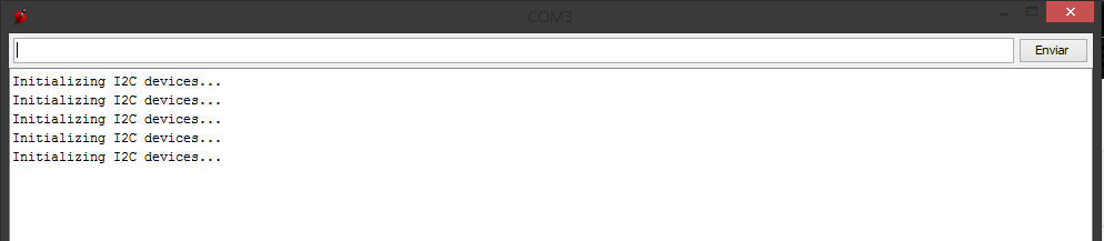
Now, when I send the first byte,i2cdev.writeByte(0x68, 0x6B, 0);, it always stuck on while(isISRComplete) {} line:
/** Write multiple bytes to an 8-bit device register.
* @param devAddr I2C slave device address
* @param regAddr First register address to write to
* @param length Number of bytes to write
* @param data Buffer to copy new data from
* @return Status of operation (true = success)
*/
bool I2Cdev::writeBytes(uint8_t devAddr, uint8_t regAddr, uint8_t length, uint8_t* data) {

UCB0I2CSA = 0x68; //only for testing

setTxBuf(regAddr); //prep the data to be sent, will be sent when the start condition is met.

UCB0CTLW0 |= UCTR | UCTXSTT;

P6OUT |= BIT0;
P6OUT &= ~BIT0;

while(isISRComplete) {} //wait until interrupt returns that it is ok to send more data
isrComplete(false);

uint8_t i;
for (i = 0; i < length; i++) {

UCB0TXBUF = data[i];
//setTxBuf(data[i]);

while(isISRComplete) {}
isrComplete(false);
}

UCB0CTLW0 |= UCTXSTP;

return 1;
}
I'd like to know if somebody faced this error before and whether could solve it.
I guess that is something wrong with the interrupt setup.
Thank you so much guys!
main code:
#include "msp.h"
#include "IMU/I2Cdev.h"
//#include "IMU/MPU6050_6Axis_MotionApps20.h"
#include "IMU/MPU6050.h"
#include <stdio.h>
#include "UART/UART_A0.h"
#include <stdint.h>
MPU6050 accelgyro;
I2Cdev i2cdev;
UART_A0 uartA0;
char debugOutput[50];
int16_t ax, ay, az;
int16_t gx, gy, gz;
void MPU9150_setupCompass();
void VCORE1();
//void eUSCIB0IsrHandler(void);
void i2c_enable_interrupt(void)
{
UCB0IE |= UCBCNTIE; /* Byte counter interrupt enable */
UCB0IE |= UCNACKIE; /* Not-acknowledge interrupt enable */
UCB0IE |= UCTXIE0; /* Transmit interrupt enable 0 */
UCB0IE |= UCRXIE0; /* Receive interrupt enable 0 */
NVIC_EnableIRQ(EUSCIB0_IRQn);
}
void main(void)
{
volatile uint32_t i;
uint32_t currentPowerState;
WDT_A->CTL = WDT_A_CTL_PW |
WDT_A_CTL_HOLD; // Stop WDT
/* Step 1: Transition to VCORE Level 1: AM0_LDO --> AM1_LDO */
/* Get current power state, if it's not AM0_LDO, error out */
currentPowerState = PCM->CTL0 & PCM_CTL0_CPM_MASK;
if (currentPowerState != PCM_CTL0_CPM_0)
while ((PCM->CTL1 & PCM_CTL1_PMR_BUSY))
;
PCM->CTL0 = PCM_CTL0_KEY_VAL | PCM_CTL0_AMR_1;
while ((PCM->CTL1 & PCM_CTL1_PMR_BUSY))
;
if (PCM->IFG & PCM_IFG_AM_INVALID_TR_IFG)
if ((PCM->CTL0 & PCM_CTL0_CPM_MASK) != PCM_CTL0_CPM_1)
/* Step 2: Configure Flash wait-state to 1 for both banks 0 & 1 */
FLCTL->BANK0_RDCTL = (FLCTL->BANK0_RDCTL & ~(FLCTL_BANK0_RDCTL_WAIT_MASK)) |
FLCTL_BANK0_RDCTL_WAIT_1;
FLCTL->BANK1_RDCTL = (FLCTL->BANK0_RDCTL & ~(FLCTL_BANK1_RDCTL_WAIT_MASK)) |
FLCTL_BANK1_RDCTL_WAIT_1;
/* Step 3: Configure DCO to 48MHz, ensure MCLK uses DCO as source*/
CS->KEY = CS_KEY_VAL; // Unlock CS module for register access
CS->CTL0 = 0; // Reset tuning parameters
CS->CTL0 = CS_CTL0_DCORSEL_5; // Set DCO to 48MHz
/* Select MCLK = DCO, no divider */
CS->CTL1 = (CS->CTL1 & ~(CS_CTL1_SELM_MASK | CS_CTL1_DIVM_MASK)) |
CS_CTL1_SELM_3;
CS->KEY = 0; // Lock CS module from unintended accesses
__enable_interrupt();
NVIC_EnableIRQ(EUSCIB0_IRQn); // Enable eUSCIB0 interrupt in NVIC module
//NVIC->ISER[0];
//NVIC_ISER0 = 1 << ((INT_EUSCIB0 - 16) & 31); // Enable eUSCIB0 interrupt in NVIC module
i2cdev.writeByte(0x68, 0x6B, 0); //wake from sleep
MPU9150_setupCompass();
//accelgyro.initialize();
//accelgyro.testConnection();
//accelgyro.setIntDataReadyEnabled(1);
while (1)
{
P6OUT |= BIT0;
P6OUT &= ~BIT0;
int i;
for (i = 10000; i > 0; i--)
{
__no_operation();
}
//accelgyro.getMotion6(&ax, &ay, &az, &gx, &gy, &gz);
i2cdev.writeByte(0x68, 0x6B, 0); //wake from sleep
//accelgyro.getAccelerationX();
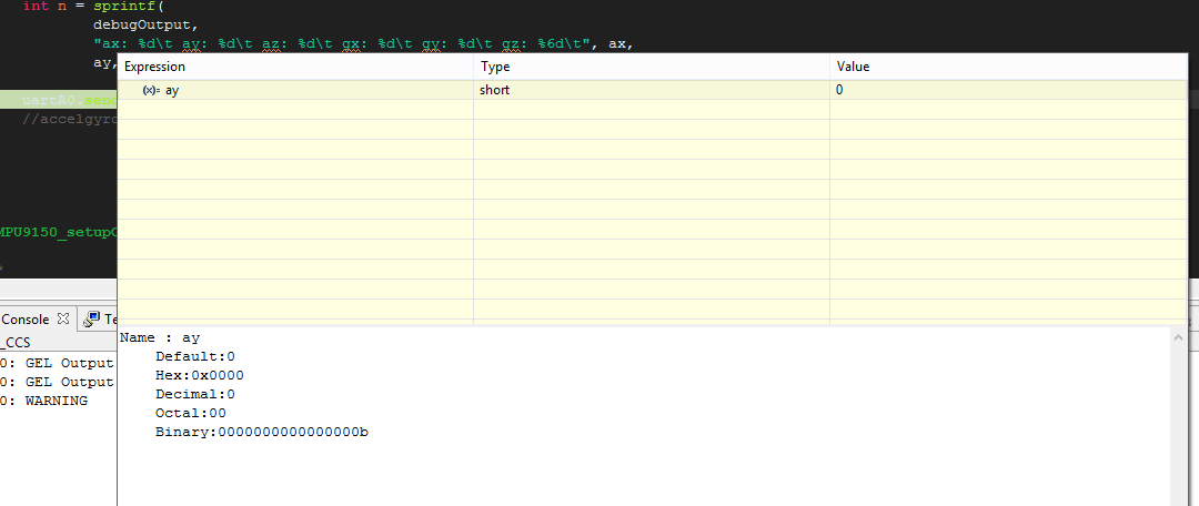
int n = sprintf(
debugOutput,
"ax: %d\t ay: %d\t az: %d\t gx: %d\t gy: %d\t gz: %6d\t", ax,
ay, az, gx, gy, gz);
uartA0.sendString(debugOutput);
//accelgyro.getIntStatus();
}
}
void MPU9150_setupCompass()
{
/*
//UCB0CTLW0 |= UCSWRST;
UCB0I2CSA = MAG_I2C_ADDRESS; //change Adress to Compass
//UCB0CTLW0 &= ~UCSWRST;
i2cdev.writeByte(0x68, 0x0A, 0x00); //PowerDownMode
i2cdev.writeByte(0x68, 0x0A, 0x0F); //SelfTest
i2cdev.writeByte(0x68, 0x0A, 0x00); //PowerDownMode
*/
//UCB0CTLW0 |= UCSWRST;
UCB0I2CSA = ACCEL_GYRO_I2C_ADDRESS
; //change Adress to Compass
//UCB0CTLW0 &= ~UCSWRST;
i2cdev.writeByte(0x68, 0x24, 0x40); //Wait for Data at Slave0
i2cdev.writeByte(0x68, 0x25, 0x8C); //Set i2c address at slave0 at 0x0C
i2cdev.writeByte(0x68, 0x26, 0x02); //Set where reading at slave 0 starts
i2cdev.writeByte(0x68, 0x27, 0x88); //set offset at start reading and enable
i2cdev.writeByte(0x68, 0x28, 0x0C); //set i2c address at slv1 at 0x0C
i2cdev.writeByte(0x68, 0x29, 0x0A); //Set where reading at slave 1 starts
i2cdev.writeByte(0x68, 0x2A, 0x81); //Enable at set length to 1
i2cdev.writeByte(0x68, 0x64, 0x01); //overvride register
i2cdev.writeByte(0x68, 0x67, 0x03); //set delay rate
i2cdev.writeByte(0x68, 0x01, 0x80);
i2cdev.writeByte(0x68, 0x34, 0x04); //set i2c slv4 delay
i2cdev.writeByte(0x68, 0x64, 0x00); //override register
i2cdev.writeByte(0x68, 0x6A, 0x00); //clear usr setting
i2cdev.writeByte(0x68, 0x64, 0x01); //override register
i2cdev.writeByte(0x68, 0x6A, 0x20); //enable master i2c mode
i2cdev.writeByte(0x68, 0x34, 0x13); //disable slv4
}
**Attention** This is a public forum