This thread has been locked.

If you have a related question, please click the "Ask a related question" button in the top right corner. The newly created question will be automatically linked to this question.

MSP430FR2033: Minimizing current consumption of blank part: 4-wire JTAG pins {TCK,TMS,TDI,TDO}

Part Number: MSP430FR2033
Other Parts Discussed in Thread: MSP430F1121A

Hello,
Could you please advise an external circuit that satisfies:

  • minimum current consumption for blank part.   (The FRAM contents are not programmed after ship from TI.)
  • 4-wire JTAG terminals are available for CCS to debug-run.


We would like to be concentrated on the external circuit for 4-wire JTAG pins.
I would think the solution would be a resistor (like 1M_ohms) for each JTAG pins, {TCK,TMS,TDI,TDO}. Do you agree?


Background:
My customer board will be assembled with a battery and spend a pretty long time before programming.
Therefore our point is the power consumption with the blank part.

UG slau445g tells that {TCK,TMS,TDI,TDO} should be opened for 4-wire JTAG. (see 1.6 Connection of Unused Pins.)
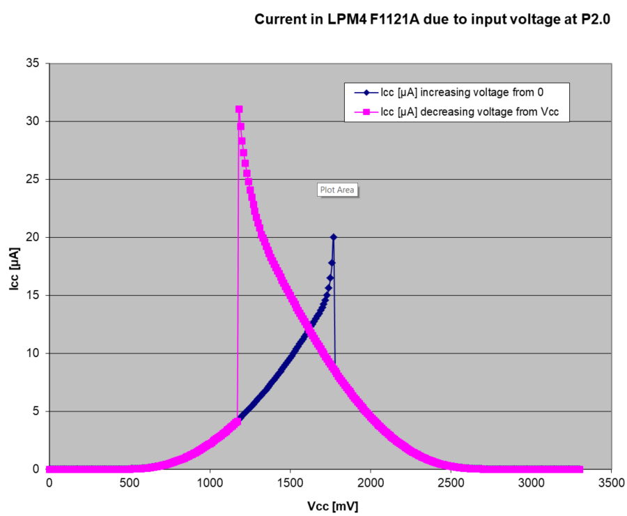
On the other hand, accorgding to customer tests, {TCK,TMS,TDI} needed to be pulled-down to get LPM4 low current.


Then we thought that:

  • It would be necessary to pull-up or pull-down JTAG signals {TCK,TMS,TDI} to minimize the current consumption with a blank parts.
  • No idea for TDO. Could you please advise also?
  • The pull-up/-down resistor value should be larger enough to accept JTAG connections.


Thank you.

  • Hello,
    according to our documentation and the section you mentioned, the JTAG pins should be left open, and an empty device should automatically enter LPM4.
    But the main problem with low current consumption will most probably result from non terminated GPIOs, which will be floating.

    Irrespective of that, you need to be careful with applying external resistors, as some of the JTAG pins have internal ones.

    I'll double check on the JTAG pins, and come back to you on that portion.

    Best regards
    Peter
  • Hello,
    coming back to this, and double checking with the datasheet of the MSP430FR2033 I can make the following additional statements:
    1. The MSP430FR2033 has shared JTAG pins, means the JTAG interface is shared with GPIO and other functions.
    2. The default state, means if not running the debug initialization sequence on Reset and Test pin, the device is not activating the JTAG functionality, thus if measuring any current change due to termination of the pins with JTAG functionality, this is not related to JTAG function of those pins, but related to the floating node behavior of the GPIO input function of those pins.
    3. The User's Guide recommendation for unused pins remains valid, but in the case of shared JTAG pins, the previous point needs to be considered.
    4. The automatic run into LPM4 of empty devices is not intended to minimize current consumption of non programmed devices, but to ensure maximum possible safety of applications, where the device needs to be programmed in-circuit, with a completely populated board. Thus the CPU is turned off and all GPIOs remain in input direction, to avoid erroneous drive of external components, like e.g. an H-Bridge of a motor or similar critical things. Thus it cannot avoid scenarios where floating nodes can result in relatively high current consumption. Keeping in mind a single floating node might be responsible for up to several 100s of µA-s the only possibility with a scenario, where a battery is supplying an non-programmed device, is to ensure termination of all GPIOs by external circuitry.

    Best regards
    Peter
  • Peter,
    Thank you for your reply.
    Please review my summary:
    The current of a floating GPIO is sometimes 100s of µA. To pull-down this current, the pull-down resistor should be like 0.5V/1mA = 500ohms or smaller. But such a smaller resistors should not be put on the 4-wire JTAG pins.

    I was surprised to the large current, 100s of uA. I hope my summary is not correct.
  • Hello Hideaki,

    sorry for not being exploratory enough on this.

    The current resulting from a floating node is not flowing into or out of the respective pin. This current is caused by the extremely high input impedance and the resulting charge on the input, pushing the input voltage to intermediate voltage levels, somewhere between GND and supply voltage level of the MSP430.

    For better understanding please see a measurement example of a MSP430F1121A, when applying intermediate voltage levels to a GPIO configured as input.

    This is just one example for one device, at room temperature, and one GPIO.

    As stated, this current is not flowing in or out of the pin, but is the cross current, which flows through the n- and p-stage of a driver, as with intermediate signal levels both stages are not perfectly shut off, and thus opening a current path from supply towards GND.

    In terms of the resistance value, required for termination of such a floating node, you do not need to compensate this current, but only the leakages, which are responsible for driving the respective input to the critical voltage range. This is on one hand the MSP430 input leakage, which is specified with +/-20nA for the MSP430FR2033 in it's datasheet, and on the other hand leakage currents to that pin from PCB. This resistor needs to handle only those currents, keeping the voltage at the GPIO sufficiently close to GND or supply voltage. It is in input mode of the GPIO not causing any additional currents, other than leakages through the GPIO, connected logic and PCB leakages. Thus usually can be of very high values, up to MOhm range.

    So no critical values applied to JTAG or other GPIO pins are required.

    I hope this clarifies your point.

    Best regards

    Peter

  • Peter,
    Thank you again for your reply.
    To summarize, do you agree the idea to put, for example, 1Mohm, to each JTAG-GPIO pins {TCK,TMS,TDI,TDO} ?


    Please be noted the requirements are:
    - Minimum current consumption for blank part. (The FRAM contents are not programmed after ship from TI.)
    - 4-wire JTAG terminals are available for CCS to debug-run.
  • Hi Hideaki,
    that's correct for the shared JTAG pins of the MSP430FR2033, P1.4/P1.5/P1.6/P1.7. The 1 MOhm is sufficient to prevent the GPIOs from floating causing respective currents. The pull-up direction is the better one, as this is also the direction of the programming tools.
    As mentioned before, please keep in mind, every GPIO, if not terminated externally, can float and generate respective currents. So to prevent issues with unwanted current consumption with non programmed devices, all GPIOs need a termination.

    Best regards
    Peter
  • Peter,
    Thank you very much for kind replies. We understood.
  • Hello Hideaki,
    you're welcome. I am closing the thread, as your reply has re-opened it. A reply after clicking the resolved button does this....

    Best regards
    Peter
  • Peter,

    Let me reconfirm that 1Mohm pull-ups for each pins {P1.4/P1.5/P1.6/P1.7} are safe for 4-wire JTAG communication.

    Your post at [2019/2/28 7:49 PM] commented about "keeping GPIO pull-up/down". Thank you very much. It is the 1st point.
    So I would ask your comment about the 2nd point, that is, the JTAG communication.

    Thank you for your time again,

    -n

  • Hello Hideaki,
    1MOhm pull-up resistors on each of the shared JTAG pins will not generate any issues with JTAG programming and be sufficient for the termination of the GPIOs.
    I just tested it with HW successfully.

    Best regards
    Peter

**Attention** This is a public forum