This thread has been locked.

If you have a related question, please click the "Ask a related question" button in the top right corner. The newly created question will be automatically linked to this question.

MSP430G2101: Jitter issue

Part Number: MSP430G2101

Hi

We have an issue in our push-button application where we use the MSP430G2101IPW14. Communication is done over SPI which is very time critical. We have found out that in some push-buttons there is an SPI communication timing issue and the buttons return incorrect data. Our assumption is that the MSP has an issue as we have tried to rule out all other possible error generating factors. The microcontroller is using its internal oscillator.

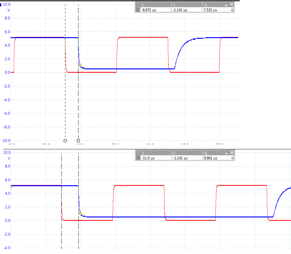
We have tested some fully functional buttons and some failing buttons from our production line. Observations of failing operation can be detected from the attached scope-plots with SPI clock signal on the input and data on the output– there is a noticeable jitter in the failing buttons which causes the problems in our system.

When heating up the MSP with hot air (approx. 100’C) in the failing buttons we have seen that the jitter disappears. We suspect that the problems disappear as the forced heat increases the clock frequency resulting in faster SPI communication and hence the communication delay time decreases.

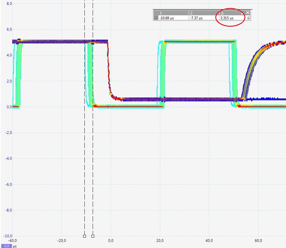
Please find attached the scope-plots where you can see the SPI clock and the data output signal in the same picture. In a fully functional system, there is no jitter as you can see from the plots, in the other plot there is a 3.3us jitter which causes problems in our production.

Have you seen such behavior in the MSP430G2101IPW14 before? What could possibly be wrong here? Please advice

Jitter.pdf

  • Is the G2101 the (SPI) master or slave? Does the Data line in the scope trace(s) correspond to MISO or MOSI?

    I wouldn't call this effect "jitter" so much as "someone (presumably the slave) missing a clock entirely". 

    The G2101 doesn't have a USCI or USI [Ref data sheet (SLAS695I)], so I suppose you''re doing SPI in software. If you're not using the calibrated clock constants (CAL[DCO/BC1]_1MHZ), different chips will (in general) run at slightly different speeds.

  • Hi Kenka,

    Bruce makes some good points (thanks, Bruce!). 

    I think answering his questions can benefit us. Just to reiterate:

    1. Is the G2101 the SPI master or slave? What is the other device it is talking to?

    2. Is the scope picture showing the MISO or MOSI line?

    3. Are you using the calibrated clock constants?

    Thanks,

    Mitch

  • Hi Mitch and Bruce,

    Thanks for your comments and additional questions, Please find my comments below:

    • Is the G2101 the SPI master or slave? What is the other device it is talking to?

    G2101 is SPI slave. It is talking to one master device (different MCU with a Cortex core). There can be multiple slaves in the same bus. All devices have 74-family drivers on the bus side.

    • Is the scope picture showing the MISO or MOSI line?

    The scope is showing CLK and MISO lines, measured in persistence mode (Using Picoscope 5444)

    • Are you using the calibrated clock constants?

    This is an existing product that has been in production for quite some time. As far as we were able to find from old SW source codes, calibrated clock constant is not in use.

    Below I have added further comments, why I believe there is something wrong with specifically this particular device, and not a general design fault in sw or hw.

    I have attached a new oscilloscope picture. Picture named "1.png" shows two separate measurements from the one failing device. Red channel is the clock signal, and blue channel is the MISO. It can be seen that delay between CLK signal active (LOW) to MISO signal active (LOW) is changing between the two measurements (7.531uS and 9.861uS). On a correctly working device this delay is constant.

    I have re-attached the previous persistence measurement pics with better resolution and better cropping as "2.jpg" from the failing device, and "3.jpg" from a correctly working device. All measurements are done with devices connected to the same SPI bus, with the same master device.


  • Glancing through the data sheet (SLAS695I) I don't see a specification for the un-calibrated clock speed. My guess is that you've happened on one of the outliers, though we can't really claim it's "out of spec" since (as near as I can tell) there is no spec.

    It really looks as though the failing device is running slow (late) and misses the second clock (rising edge) entirely.It's hard to know without seeing the code.

    Unsolicited: If I had such a critical deadline, I would not only use the calibrated clock constant (to control variability) but also try to run even faster to make sure I didn't miss anything. Though the G2101 only provides a calibrated 1MHz from the factory, it is possible to generate the higher-speed constants using an external 32kHz clock and Example msp430g2xx1_dco_flashcal.c

  • Hi Bruce,

    Thanks for your comments on this issue. I am the customer who is having this timing issue with the G2101 (thank you Kenka for relaying my previous messages).

    I agree that the G2101 is probably missing the second clock edge, which in turn causes wrong data in the communication. I cannot paste the source code here, but we have verified that the device is doing other tasks between the CLK edges. Missing clock edge seems a very likely cause for the problems we encounter in our system.

    However, I don't understand how one device (correctly working device) is showing absolutely constant delay between CLK signal edge to MISO signal edge. The failing device is having clear variance between this timing. Just to clarify, even the failing device is working correctly intermittently, but more often it is not working.

    I would imagine if the clock was running slow, the delay between signal transitions would be slower, but still repeatable. To me it looks like the clock is not stable on the failing device. Could it be a defective device? I have provided the troublesome unit to local TI support for further investigation.

  • I was looking at the time scale: At (roughly) 1MHz, 3us is a single instruction (average; range 1-6us). It's not hard to imagine code with a loop that, due to slow(-ish) clock, just barely misses a signal edge, and thus pushes the entire schedule forward by a loop-size quantum. 

    That said: Since you have an FAE to work with, that's the person to listen to. (I'm in the privileged position of Not facing a stalled assembly line.) I hope you'll let us know how it turns out

  • Hi Kenka,

    I will go ahead and close out this thread since we are handling this internally. I will re-open when we have more information to share.

    Thanks,

    Mitch

**Attention** This is a public forum