This thread has been locked.
If you have a related question, please click the "Ask a related question" button in the top right corner. The newly created question will be automatically linked to this question.
Tool/software: Code Composer Studio
Hello,
we have a strange problem with I2C bus on our board.
We use among other the components:
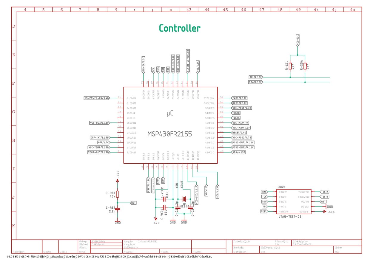
MSP430FR2155
On I2C: two EEPROM STM M24512, one Accelerometer Kionix KX122-1037
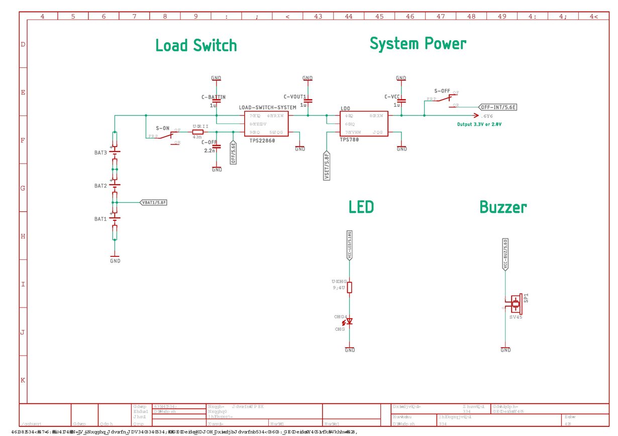
Pull Up , 4,7kOhm, Pull Up are supplied to the controller, not directly from Vcc,
Bus Capacitance measured on pcb without components SDA to GND 4,1pf, SCL to GND 4,0pF and SDA to SCL 3,5pf
Length of the Wire less then 40mm
We produce 50 boards and on 28 boards, our code stuck with the first I2C Communication. We found that the Controller does not pull down the SDA to GND, no start condition was released.
On some of these boards we remove the Accelerometer and then the code runs.
Then we flashed the sample Code from TI on one of the faulty boards. Also with this code no start condition was released. Both SDA and SCL held on 3.3V.
During debugging we notice, when we set some breakpoints then the code works. At the end, we include a delay loop. With the delay it works, without not.
Do you have any ideas what's could be wrong on the board?
The sample code from TI was slightly modified to set the P2.4 to high for suppling the pull up's and change from Port 0 to 1
* --/COPYRIGHT--*/
//******************************************************************************
// MSP430FR235x Demo - eUSCI_B0 I2C Master TX bytes to Multiple Slaves
//
// Description: This demo connects two MSP430's via the I2C bus.
// The master transmits to 4 different I2C slave addresses 0x0A,0x0B,0x0C&0x0D.
// Each slave address has a specific related data in the array TXData[].
// At the end of four I2C transactions the slave address rolls over and begins
// again at 0x0A.
// ACLK = REFO = 32768Hz, MCLK = SMCLK = default DCO = ~1MHz
// Use with msp430fr235x_uscib0_i2c_16.c
//
// /|\ /|\
// MSP430FR2355 10k 10k MSP430FR2355
// slave | | master
// ----------------- | | -----------------
// | P1.2/UCB0SDA|<-|----|->|P1.2/UCB0SDA |
// | | | | |
// | | | | |
// | P1.3/UCB0SCL|<-|------>|P1.3/UCB0SCL |
// | | | |
//
// Cash Hao
// Texas Instruments Inc.
// November 2016
// Built with IAR Embedded Workbench v6.50.0 & Code Composer Studio v6.2.0
//******************************************************************************
#include <msp430.h>
unsigned char TXData[]= {0xA1,0xB1,0xC1,0xD1}; // Pointer to TX data
unsigned char SlaveAddress[]= {0x0A,0x0B,0x0C,0x0D};
unsigned char TXByteCtr;
unsigned char SlaveFlag = 0;
int main(void)
{
WDTCTL = WDTPW | WDTHOLD; // Stop watchdog timer
// Configure Pins for I2C
P4SEL0 |= BIT7 | BIT6; // I2C pins
P2SEL0 &= ~BIT4; // I2C Power pins
P2SEL1 &= ~BIT4; // I2C Power pins
P2DIR |= BIT4; // I2C Power pins
P2OUT |= BIT4; // I2C Power pins
// Disable the GPIO power-on default high-impedance mode
// to activate previously configured port settings
PM5CTL0 &= ~LOCKLPM5;
// Configure USCI_B0 for I2C mode
UCB1CTLW0 |= UCSWRST; // put eUSCI_B in reset state
__delay_cycles(50000); // additional Delay
UCB1CTLW0 |= UCMODE_3 | UCMST; // I2C master mode, SMCLK
UCB1BRW = 0x8; // baudrate = SMCLK / 8
UCB1CTLW0 &=~ UCSWRST; // clear reset register
UCB1IE |= UCTXIE0 | UCNACKIE; // transmit and NACK interrupt enable
SlaveFlag =0;
while(1)
{
__delay_cycles(1000); // Delay between transmissions
UCB1I2CSA = SlaveAddress[SlaveFlag]; // configure slave address
TXByteCtr = 1; // Load TX byte counter
while (UCB1CTLW0 & UCTXSTP); // Ensure stop condition got sent
UCB1CTLW0 |= UCTR | UCTXSTT; // I2C TX, start condition
__bis_SR_register(LPM0_bits | GIE); // Enter LPM0 w/ interrupts
// Remain in LPM0 until all data
// is TX'd
// Change Slave address
SlaveFlag++;
if (SlaveFlag>3) // Roll over slave address
{
SlaveFlag =0;
}
}
}
#if defined(__TI_COMPILER_VERSION__) || defined(__IAR_SYSTEMS_ICC__)
#pragma vector = USCI_B1_VECTOR
__interrupt void USCIB1_ISR(void)
#elif defined(__GNUC__)
void __attribute__ ((interrupt(USCI_B1_VECTOR))) USCIB1_ISR (void)
#else
#error Compiler not supported!
#endif
{
switch(__even_in_range(UCB1IV,USCI_I2C_UCBIT9IFG))
{
case USCI_NONE: break; // Vector 0: No interrupts break;
case USCI_I2C_UCALIFG: break;
case USCI_I2C_UCNACKIFG:
UCB1CTL1 |= UCTXSTT; //resend start if NACK
break; // Vector 4: NACKIFG break;
case USCI_I2C_UCSTTIFG: break; // Vector 6: STTIFG break;
case USCI_I2C_UCSTPIFG: break; // Vector 8: STPIFG break;
case USCI_I2C_UCRXIFG3: break; // Vector 10: RXIFG3 break;
case USCI_I2C_UCTXIFG3: break; // Vector 14: TXIFG3 break;
case USCI_I2C_UCRXIFG2: break; // Vector 16: RXIFG2 break;
case USCI_I2C_UCTXIFG2: break; // Vector 18: TXIFG2 break;
case USCI_I2C_UCRXIFG1: break; // Vector 20: RXIFG1 break;
case USCI_I2C_UCTXIFG1: break; // Vector 22: TXIFG1 break;
case USCI_I2C_UCRXIFG0: break; // Vector 24: RXIFG0 break;
case USCI_I2C_UCTXIFG0:
if (TXByteCtr) // Check TX byte counter
{
UCB1TXBUF = TXData[SlaveFlag]; // Load TX buffer
TXByteCtr--; // Decrement TX byte counter
}
else
{
UCB1CTLW0 |= UCTXSTP; // I2C stop condition
UCB1IFG &= ~UCTXIFG; // Clear USCI_B0 TX int flag
__bic_SR_register_on_exit(LPM0_bits); // Exit LPM0
}
break; // Vector 26: TXIFG0 break;
case USCI_I2C_UCBCNTIFG: break; // Vector 28: BCNTIFG
case USCI_I2C_UCCLTOIFG: break; // Vector 30: clock low timeout
case USCI_I2C_UCBIT9IFG: break; // Vector 32: 9th bit
default: break;
}
}
Hello,
Thank you for reaching out to us, we are starting to look into the issue.
All the best,
Colin Adema
Hello,
If possible, could you send an oscilloscope screenshot of trying to get a start condition on both a working board and a non-working board?
All the best,
Colin Adema
Hello Collin,
Attached you will find a screen shot from a working board. SDA is the yellow line and SCL the blue one.
From the non-working board we have not measurement, because there are no changes on the line.
In the meantime, we found out that on the non –working boards the busy bit UCBBUSY was set to high = busy during the initialization.
For example, when we go step-by-step through the code
01 // Step 1 Set SW reset
02 UCB1CTLW0 |= UCSWRST;
03 // Step 2 Initialize all eUSCI_B registers with UCSWRST = 1 (including UCxCTL1).
04 UCB1CTLW0 |= UCMST + UCMODE_3;// + UCSYNC; // I2C Master, synchronous mode
05 UCB1CTLW0 |= UCSSEL_2 | UCTR; // Use SMCLK, TX mode, keep SW reset
After Line 04 the bit was set.
That is the reason why the controller does not generate the start condition.
Up to now did not find any signals on the I2C like a start condition that could set the bit.
It is not clear why the UCBBUSY Bit was set.
Regards Andreas
Additional we observe the interrupt flags 6 and 7 from port 4 change in arbitrates way
The board is battery power (3 Alkaline AA Cells), the voltage is regulated by a TPS780, we just use 3.3V. The first Cell is connected the ADC and the off Pin from the TPS22860 Load Switch is connected to an Output Pin from the µC
Hello,
Could you double check that you've attached the screenshots? I don't believe I see them.
All the best,
Colin Adema
Hello,
After doing some testing, I found that shorting either SCL or SDA to ground upon initializing the I2C on startup causes the busy flag to be set before any data is sent. Is it possible that your board is briefly shorting the lines to ground on startup while initializing the I2C before pulling them to Vcc?
Could you send an oscilloscope screenshot of your board during startup?
All the best,
Colin Adema
Dear Colin,
Thank you for your reply.
Indeed, we found some unexpected high –low changes during die power up sequence of the accelerometer. We eliminated this by switching the accelerometer on before we initialize the I2C. However, we have still the problem, that the UCBBUSY Bit was set.
We already measured some spikes on the bus. One of them is shown in the picture below. Up to now, we are not able to determine which statement in the code or which component on the bus cause these spikes. Because the behaviour of the circuit with and without debugger is different. When we go with the debugger step-by-step through the code, everything works fine and no UCBBUSY Bit was set. When we let run the program we can just measure such spikes but get no correlation to the possible "source".
Let me know if you need further measurement.
Do you have any suggestion for a quick workaround to prevent the µC to set the bit and do you have an idea how we can find out what cause these spike (if these spikes are the reason for setting the UCBBUSY)
Thank you
Andreas
Spike:
Start Condition
Communication enlarged
Hello,
Is there any particular reason why you're powering the I2C from the microcontroller instead of directly from the output of the LDO? It's possible that switching noise on the I2C is causing some problems on the power pin.
All the best,
Colin Adema
Hello Colin,
many thanks for the answer.
The reason was actually power saving, since I2C should not be used constantly.
We had already connected the pull-up resistors directly to the LDO, without any improvement. We will repeat this and disconnect the pin from the μC.
However, I do not know why switching noise from the bus can have a retroactive effect on the μC, especially on the eUSCI_xx module. Or have I misunderstood that?
Regards
Hello,
If the code works when stepping through your code and not when it just runs without debugging, then you could try putting delay statements after each line of code in the initialization to sort of mimic stepping through the code and try to narrow which one, if any, causes the spike.
In regard to the switching noise, the switching on the I2C could cause a small voltage ripple on the pin you've assigned to power via crosstalk of the pins.However, this difference should be on the order of millivolts and therefore shouldn't affect the pin on the order of the spike you're recording. This is likely not the issue but it was worth checking for just in case it led to a different error in the way the pull ups were receiving power.
All the best,
Colin Adema
Hello,
How has the issue been? Has it been resolved?
All the best,
Colin Adema
Hello Collin,
Thanks for the answer.
We have not been able to find the cause or source for the spikes so far.
We test if the busy bit is set and if it is set we re-initialize the interface. That's not good, but we do not know a better solution.
We think about a re-design of the board.
Can you recommend another μC that has no misinterpretation of the start condition?
What's more energy efficient I2C or SPI? We could switch to SPI with the Accelerometer and the EEPROMS.
Regards
Andreas
Hello,
The I2C peripheral is part of the USCI and eUSCI interface, which is standard across all of our microcontrollers. Therefore, using a different microcontroller on the same board will likely have the same issue with I2C.
As far as the power consumption goes, SPI uses less power on average due to the lack of pull-up resistors, so switching to that would be a safe bet.
Let me know if you have any more questions.
All the best,
Colin Adema
**Attention** This is a public forum