This thread has been locked.
If you have a related question, please click the "Ask a related question" button in the top right corner. The newly created question will be automatically linked to this question.
Part Number: MSP432P401R
Tool/software: Code Composer Studio
Hi,
We have encountered a strange issue programming a custom board based on the 64-pin MSP432P401RIRGCR. Initial development of the firmware was completed on the 100-pin MSP432 launchpad with no issues. After receiving proto boards, we confirmed the boards were functional by programming them using CCS with a standard TI example: gpio_toggle_output_MSP_EXP432P401R_nortos_gcc
However, after we booted our custom firmware running TI-RTOS onto the proto boards, we have seemingly bricked the micro and are unable to factory reset the devices.
The sequence of steps that led to the failure were:
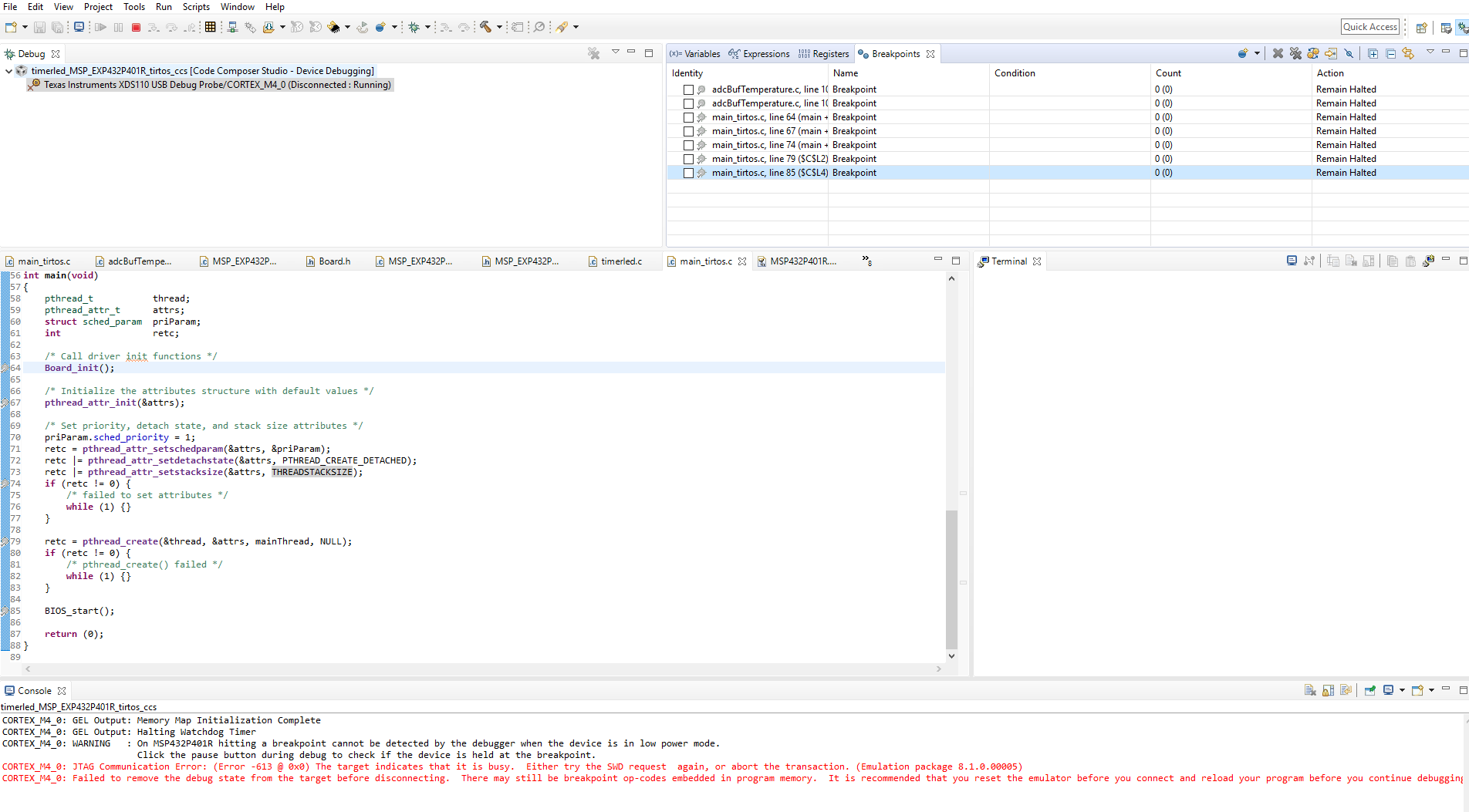
1. Custom firmware was loaded via CCS debug option
2. After successfully being programmed, standard resume / terminate options in CCS pop up as normal, indicating program is ready to run.
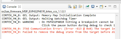
3. After selecting resume, we get the error shown below in the console after a few seconds
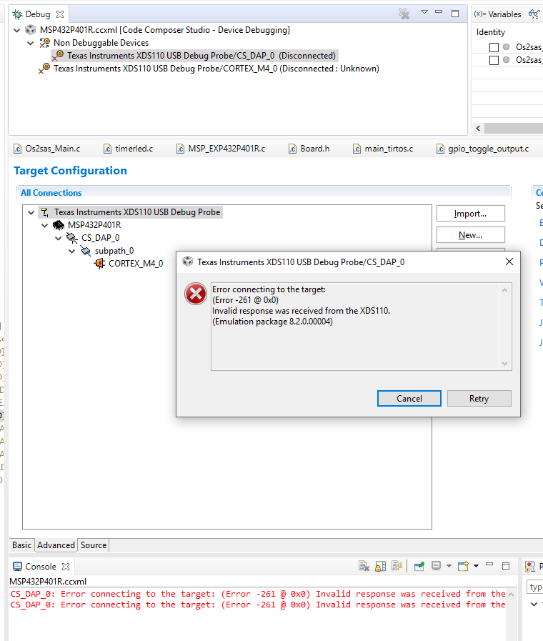
At this point the board cannot be factory reset by the standard procedure. Once you select the Target Configuration (Launch selected configuration) -> show all cores and then select "Connect", you get the following error:
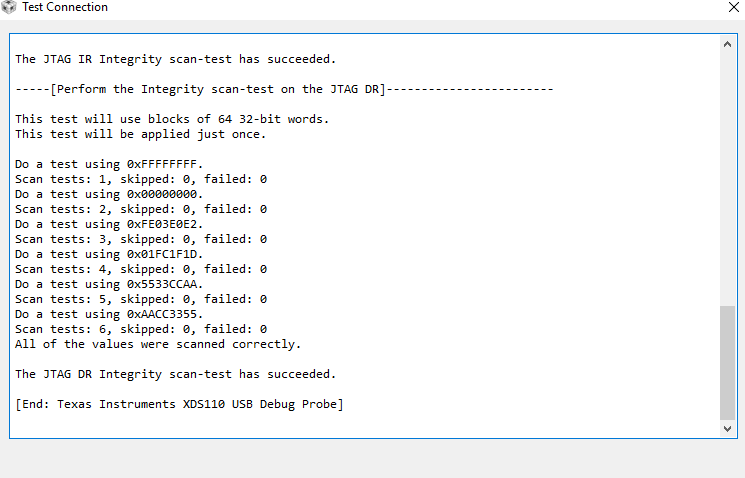
However, when you test the JTAG connection via target configuration, the JTAG integrity test succeeds which means the XDS110 still sees the MSP432.
As far as I am aware, there are no special steps required within the project to port the firmware from a 100-pin to a 64-pin MSP432. Is this correct? Both the launchpad and the MSP432P401RIRGCR have the same amount of Flash and RAM.
I have also attached our MSP_EXP432P401R.c/MSP_EXP432P401R.h files which maps the hardware on the custom board to our hardware abstracted firmware.
/* * Copyright (c) 2015-2018, Texas Instruments Incorporated * All rights reserved. * * Redistribution and use in source and binary forms, with or without * modification, are permitted provided that the following conditions * are met: * * * Redistributions of source code must retain the above copyright * notice, this list of conditions and the following disclaimer. * * * Redistributions in binary form must reproduce the above copyright * notice, this list of conditions and the following disclaimer in the * documentation and/or other materials provided with the distribution. * * * Neither the name of Texas Instruments Incorporated nor the names of * its contributors may be used to endorse or promote products derived * from this software without specific prior written permission. * * THIS SOFTWARE IS PROVIDED BY THE COPYRIGHT HOLDERS AND CONTRIBUTORS "AS IS" * AND ANY EXPRESS OR IMPLIED WARRANTIES, INCLUDING, BUT NOT LIMITED TO, * THE IMPLIED WARRANTIES OF MERCHANTABILITY AND FITNESS FOR A PARTICULAR * PURPOSE ARE DISCLAIMED. IN NO EVENT SHALL THE COPYRIGHT OWNER OR * CONTRIBUTORS BE LIABLE FOR ANY DIRECT, INDIRECT, INCIDENTAL, SPECIAL, * EXEMPLARY, OR CONSEQUENTIAL DAMAGES (INCLUDING, BUT NOT LIMITED TO, * PROCUREMENT OF SUBSTITUTE GOODS OR SERVICES; LOSS OF USE, DATA, OR PROFITS; * OR BUSINESS INTERRUPTION) HOWEVER CAUSED AND ON ANY THEORY OF LIABILITY, * WHETHER IN CONTRACT, STRICT LIABILITY, OR TORT (INCLUDING NEGLIGENCE OR * OTHERWISE) ARISING IN ANY WAY OUT OF THE USE OF THIS SOFTWARE, * EVEN IF ADVISED OF THE POSSIBILITY OF SUCH DAMAGE. */ /* * ======== MSP_EXP432P401R.c ======== * This file is responsible for setting up the board specific items for the * MSP_EXP432P401R board. */ #include <stdbool.h> #include <stddef.h> #include <stdint.h> #ifndef DeviceFamily_MSP432P401x #define DeviceFamily_MSP432P401x #endif #include <ti/devices/DeviceFamily.h> #include <ti/drivers/Power.h> #include <ti/drivers/power/PowerMSP432.h> #include <ti/devices/msp432p4xx/inc/msp.h> #include <ti/devices/msp432p4xx/driverlib/rom.h> #include <ti/devices/msp432p4xx/driverlib/rom_map.h> #include <ti/devices/msp432p4xx/driverlib/adc14.h> #include <ti/devices/msp432p4xx/driverlib/dma.h> #include <ti/devices/msp432p4xx/driverlib/gpio.h> #include <ti/devices/msp432p4xx/driverlib/i2c.h> #include <ti/devices/msp432p4xx/driverlib/interrupt.h> #include <ti/devices/msp432p4xx/driverlib/pmap.h> #include <ti/devices/msp432p4xx/driverlib/ref_a.h> #include <ti/devices/msp432p4xx/driverlib/spi.h> #include <ti/devices/msp432p4xx/driverlib/timer_a.h> #include <ti/devices/msp432p4xx/driverlib/timer32.h> #include <ti/devices/msp432p4xx/driverlib/uart.h> #include <ti/devices/msp432p4xx/driverlib/wdt_a.h> #include "MSP_EXP432P401R.h" /* * =============================== ADC =============================== */ #include <ti/drivers/ADC.h> #include <ti/drivers/adc/ADCMSP432.h> /* ADC objects */ ADCMSP432_Object adcMSP432Objects[MSP_EXP432P401R_ADCCOUNT]; /* ADC configuration structure */ const ADCMSP432_HWAttrsV1 adcMSP432HWAttrs[MSP_EXP432P401R_ADCCOUNT] = { { .adcPin = ADCMSP432_P5_0_A5, .refVoltage = ADCMSP432_REF_VOLTAGE_VDD, .resolution = ADC_14BIT }, { .adcPin = ADCMSP432_P5_1_A4, .refVoltage = ADCMSP432_REF_VOLTAGE_VDD, .resolution = ADC_14BIT }, { .adcPin = ADCMSP432_P5_2_A3, .refVoltage = ADCMSP432_REF_VOLTAGE_VDD, .resolution = ADC_14BIT }, { .adcPin = ADCMSP432_P5_5_A0, .refVoltage = ADCMSP432_REF_VOLTAGE_VDD, .resolution = ADC_14BIT } }; const ADC_Config ADC_config[MSP_EXP432P401R_ADCCOUNT] = { { .fxnTablePtr = &ADCMSP432_fxnTable, .object = &adcMSP432Objects[MSP_EXP432P401R_ADC0], .hwAttrs = &adcMSP432HWAttrs[MSP_EXP432P401R_ADC0] }, { .fxnTablePtr = &ADCMSP432_fxnTable, .object = &adcMSP432Objects[MSP_EXP432P401R_ADC1], .hwAttrs = &adcMSP432HWAttrs[MSP_EXP432P401R_ADC1] }, { .fxnTablePtr = &ADCMSP432_fxnTable, .object = &adcMSP432Objects[MSP_EXP432P401R_ADC2], .hwAttrs = &adcMSP432HWAttrs[MSP_EXP432P401R_ADC2] }, { .fxnTablePtr = &ADCMSP432_fxnTable, .object = &adcMSP432Objects[MSP_EXP432P401R_ADC3], .hwAttrs = &adcMSP432HWAttrs[MSP_EXP432P401R_ADC3] } }; const uint_least8_t ADC_count = MSP_EXP432P401R_ADCCOUNT; /* * =============================== ADCBuf =============================== */ #include <ti/drivers/ADCBuf.h> #include <ti/drivers/adcbuf/ADCBufMSP432.h> /* ADC objects */ ADCBufMSP432_Object adcbufMSP432Objects[MSP_EXP432P401R_ADCBUFCOUNT]; ADCBufMSP432_Channels adcBuf0MSP432Channels[MSP_EXP432P401R_ADCBUF0CHANNELCOUNT] = { { .adcPin = ADCBufMSP432_P5_0_A5, .refSource = ADCBufMSP432_VREFPOS_INTBUF_VREFNEG_VSS, .refVoltage = 3300000, .adcInputMode = ADCBufMSP432_SINGLE_ENDED, //ADCBufMSP432_DIFFERENTIAL, .adcDifferentialPin = ADCBufMSP432_PIN_NONE, .adcInternalSource = ADCBufMSP432_INTERNAL_SOURCE_MODE_OFF }, { .adcPin = ADCBufMSP432_P5_1_A4, .refSource = ADCBufMSP432_VREFPOS_INTBUF_VREFNEG_VSS, .refVoltage = 3300000, .adcInputMode = ADCBufMSP432_SINGLE_ENDED, //ADCBufMSP432_DIFFERENTIAL, .adcDifferentialPin = ADCBufMSP432_PIN_NONE, .adcInternalSource = ADCBufMSP432_INTERNAL_SOURCE_MODE_OFF }, { .adcPin = ADCBufMSP432_P5_2_A3, .refSource = ADCBufMSP432_VREFPOS_INTBUF_VREFNEG_VSS, .refVoltage = 3300000, .adcInputMode = ADCBufMSP432_SINGLE_ENDED, //ADCBufMSP432_DIFFERENTIAL, .adcDifferentialPin = ADCBufMSP432_PIN_NONE, .adcInternalSource = ADCBufMSP432_INTERNAL_SOURCE_MODE_OFF }, { .adcPin = ADCBufMSP432_P5_5_A0, .refSource = ADCBufMSP432_VREFPOS_INTBUF_VREFNEG_VSS, .refVoltage = 2500000, .adcInputMode = ADCBufMSP432_SINGLE_ENDED, .adcDifferentialPin = ADCBufMSP432_PIN_NONE, .adcInternalSource = ADCBufMSP432_TEMPERATURE_MODE }, }; /* ADC configuration structure */ const ADCBufMSP432_HWAttrs adcbufMSP432HWAttrs[MSP_EXP432P401R_ADCBUFCOUNT] = { { .intPriority = ~0, .channelSetting = adcBuf0MSP432Channels, .adcTimerTriggerSource = ADCBufMSP432_TIMERA1_CAPTURECOMPARE2, .useDMA = 0, .dmaIntNum = DMA_INT0, .adcTriggerSource = ADCBufMSP432_TIMER_TRIGGER, .timerDutyCycle = 20, .clockSource = ADCBufMSP432_ADC_CLOCK } }; const ADCBuf_Config ADCBuf_config[MSP_EXP432P401R_ADCBUFCOUNT] = { { .fxnTablePtr = &ADCBufMSP432_fxnTable, .object = &adcbufMSP432Objects[MSP_EXP432P401R_ADCBUF0], .hwAttrs = &adcbufMSP432HWAttrs[MSP_EXP432P401R_ADCBUF0] } }; const uint_least8_t ADCBuf_count = MSP_EXP432P401R_ADCBUFCOUNT; /* * ============================= Capture ============================= */ #include <ti/drivers/Capture.h> #include <ti/drivers/capture/CaptureMSP432.h> CaptureMSP432_Object captureMSP432Objects[MSP_EXP432P401R_CAPTURECOUNT]; const CaptureMSP432_HWAttrs captureMSP432HWAttrs[MSP_EXP432P401R_CAPTURECOUNT] = { /* Timer_A1 */ { .timerBaseAddress = TIMER_A1_BASE, .clockSource = TIMER_A_CLOCKSOURCE_ACLK, .clockDivider = TIMER_A_CLOCKSOURCE_DIVIDER_1, .capturePort = CaptureMSP432_P7_7_TA1, .intPriority = ~0 } // }, // /* Timer_A2 */ // { // .timerBaseAddress = TIMER_A2_BASE, // .clockSource = TIMER_A_CLOCKSOURCE_ACLK, // .clockDivider = TIMER_A_CLOCKSOURCE_DIVIDER_1, // .capturePort = CaptureMSP432_P6_7_TA2, // .intPriority = ~0 // }, // /* Timer_A3 */ // { // .timerBaseAddress = TIMER_A3_BASE, // .clockSource = TIMER_A_CLOCKSOURCE_ACLK, // .clockDivider = TIMER_A_CLOCKSOURCE_DIVIDER_1, // .capturePort = CaptureMSP432_P8_2_TA3, // .intPriority = ~0 // } }; const Capture_Config Capture_config[MSP_EXP432P401R_CAPTURECOUNT] = { { .fxnTablePtr = &CaptureMSP432_captureFxnTable, .object = &captureMSP432Objects[MSP_EXP432P401R_CAPTURE_TA1], .hwAttrs = &captureMSP432HWAttrs[MSP_EXP432P401R_CAPTURE_TA1] } // }, // { // .fxnTablePtr = &CaptureMSP432_captureFxnTable, // .object = &captureMSP432Objects[MSP_EXP432P401R_CAPTURE_TA2], // .hwAttrs = &captureMSP432HWAttrs[MSP_EXP432P401R_CAPTURE_TA2] // }, // { // .fxnTablePtr = &CaptureMSP432_captureFxnTable, // .object = &captureMSP432Objects[MSP_EXP432P401R_CAPTURE_TA3], // .hwAttrs = &captureMSP432HWAttrs[MSP_EXP432P401R_CAPTURE_TA3] // } }; const uint_least8_t Capture_count = MSP_EXP432P401R_CAPTURECOUNT; /* * =============================== DMA =============================== */ #include <ti/drivers/dma/UDMAMSP432.h> static DMA_ControlTable dmaControlTable[16] __attribute__ ((aligned (256))); /* * ======== dmaErrorHwi ======== * This is the handler for the uDMA error interrupt. */ static void dmaErrorHwi(uintptr_t arg) { int status = MAP_DMA_getErrorStatus(); MAP_DMA_clearErrorStatus(); /* Suppress unused variable warning */ (void)status; while (1); } UDMAMSP432_Object udmaMSP432Object; const UDMAMSP432_HWAttrs udmaMSP432HWAttrs = { .controlBaseAddr = (void *)dmaControlTable, .dmaErrorFxn = (UDMAMSP432_ErrorFxn)dmaErrorHwi, .intNum = INT_DMA_ERR, .intPriority = (~0) }; const UDMAMSP432_Config UDMAMSP432_config = { .object = &udmaMSP432Object, .hwAttrs = &udmaMSP432HWAttrs }; /* * ============================= Display ============================= */ //zz #include <ti/display/Display.h> //zz #include <ti/display/DisplayUart.h> //zz #include <ti/display/DisplaySharp.h> //zz #define MAXPRINTLEN 1024 /* This value can be changed to 96 for use with the 430BOOST-SHARP96 BoosterPack. */ //zz #ifndef BOARD_DISPLAY_SHARP_SIZE //zz #define BOARD_DISPLAY_SHARP_SIZE 128 //zz #endif //zz DisplayUart_Object displayUartObject; //zz DisplaySharp_Object displaySharpObject; //zz //zz static char displayBuf[MAXPRINTLEN]; //zz static uint_least8_t sharpDisplayBuf[BOARD_DISPLAY_SHARP_SIZE * BOARD_DISPLAY_SHARP_SIZE / 8]; //zz const DisplayUart_HWAttrs displayUartHWAttrs = { //zz .uartIdx = MSP_EXP432P401R_UARTA0, //zz .baudRate = 115200, //zz .mutexTimeout = (unsigned int)(-1), //zz .strBuf = displayBuf, //zz .strBufLen = MAXPRINTLEN //zz }; /* ZZ const DisplaySharp_HWAttrsV1 displaySharpHWattrs = { .spiIndex = MSP_EXP432P401R_SPIB0, .csPin = MSP_EXP432P401R_LCD_CS, .powerPin = MSP_EXP432P401R_LCD_POWER, .enablePin = MSP_EXP432P401R_LCD_ENABLE, .pixelWidth = BOARD_DISPLAY_SHARP_SIZE, .pixelHeight = BOARD_DISPLAY_SHARP_SIZE, .displayBuf = sharpDisplayBuf, }; */ //zz #ifndef BOARD_DISPLAY_USE_UART //zz #define BOARD_DISPLAY_USE_UART 1 //zz #endif //zz #ifndef BOARD_DISPLAY_USE_UART_ANSI //zz #define BOARD_DISPLAY_USE_UART_ANSI 0 //zz #endif /* ZZ #ifndef BOARD_DISPLAY_USE_LCD #define BOARD_DISPLAY_USE_LCD 0 #endif */ /* * This #if/#else is needed to workaround a problem with the * IAR compiler. The IAR compiler doesn't like the empty array * initialization. (IAR Error[Pe1345]) */ //zz #if (BOARD_DISPLAY_USE_UART || BOARD_DISPLAY_USE_LCD) //zz const Display_Config Display_config[] = { //zz { //zz # if (BOARD_DISPLAY_USE_UART_ANSI) //zz .fxnTablePtr = &DisplayUartAnsi_fxnTable, //zz # else /* Default to minimal UART with no cursor placement */ //zz .fxnTablePtr = &DisplayUartMin_fxnTable, //zz # endif //zz .object = &displayUartObject, //zz .hwAttrs = &displayUartHWAttrs //zz }, //zz #endif /* ZZ #if (BOARD_DISPLAY_USE_LCD) { .fxnTablePtr = &DisplaySharp_fxnTable, .object = &displaySharpObject, .hwAttrs = &displaySharpHWattrs }, #endif */ //zz }; //zz const uint_least8_t Display_count = sizeof(Display_config) / sizeof(Display_Config); /* * ======== MSP_EXP432P401R_initGeneral ======== */ void MSP_EXP432P401R_initGeneral(void) { Power_init(); } /* * =============================== GPIO =============================== */ #include <ti/drivers/GPIO.h> #include <ti/drivers/gpio/GPIOMSP432.h> /* * Array of Pin configurations * NOTE: The order of the pin configurations must coincide with what was * defined in MSP_EXP432P401R.h * NOTE: Pins not used for interrupts should be placed at the end of the * array. Callback entries can be omitted from callbacks array to * reduce memory usage. */ GPIO_PinConfig gpioPinConfigs[] = { /* Input pins */ /* * NOTE: Specifying FALLING edge triggering for these buttons to ensure the * interrupts are signaled immediately. See the description of the * PowerMSP432 driver's automatic pin parking feature for this rationale. */ /* MSP_EXP432P401R_GPIO_S1 */ GPIOMSP432_P1_1 | GPIO_CFG_IN_PU | GPIO_CFG_IN_INT_FALLING, /* MSP_EXP432P401R_GPIO_S2 */ // GPIOMSP432_P1_4 | GPIO_CFG_IN_PU | GPIO_CFG_IN_INT_FALLING, /* MSP_EXP432P401R_SPI_MASTER_READY */ // GPIOMSP432_P5_7 | GPIO_DO_NOT_CONFIG, /* MSP_EXP432P401R_SPI_SLAVE_READY */ // GPIOMSP432_P6_0 | GPIO_DO_NOT_CONFIG, /* Output pins */ /* MSP_EXP432P401R_GPIO_LED_BLUE */ GPIOMSP432_P7_0 | GPIO_CFG_OUT_STD | GPIO_CFG_OUT_STR_LOW | GPIO_CFG_OUT_LOW, /* MSP_EXP432P401R_GPIO_LED_GREEN */ GPIOMSP432_P7_1 | GPIO_CFG_OUT_STD | GPIO_CFG_OUT_STR_HIGH | GPIO_CFG_OUT_LOW, /* * MSP_EXP432P401R_GPIO_LED_GREEN & MSP_EXP432P401R_GPIO_LED_BLUE are used for * PWM examples. Uncomment the following lines if you would like to control * the LEDs with the GPIO driver. */ /* MSP_EXP432P401R_GPIO_LED_RED */ GPIOMSP432_P7_2 | GPIO_CFG_OUT_STD | GPIO_CFG_OUT_STR_HIGH | GPIO_CFG_OUT_LOW, /* MSP_EXP432P401R_GPIO_LED_YELLOW */ GPIOMSP432_P7_3 | GPIO_CFG_OUT_STD | GPIO_CFG_OUT_STR_HIGH | GPIO_CFG_OUT_LOW, /* TMP116 EN */ // GPIOMSP432_P4_7 | GPIO_DO_NOT_CONFIG, /* MSP_EXP432P401R_SPI_CS1 */ // GPIOMSP432_P5_4 | GPIO_CFG_OUT_STD | GPIO_CFG_OUT_STR_LOW | GPIO_CFG_OUT_HIGH, /* MSP_EXP432P401R_SPI_CS2 */ // GPIOMSP432_P5_5 | GPIO_CFG_OUT_STD | GPIO_CFG_OUT_STR_LOW | GPIO_CFG_OUT_HIGH, /* MSP_EXP432P401R_SDSPI_CS */ GPIOMSP432_P4_6 | GPIO_CFG_OUT_STD | GPIO_CFG_OUT_STR_LOW | GPIO_CFG_OUT_HIGH, /* Sharp Display - GPIO configurations will be done in the Display files */ //ZZ GPIOMSP432_P4_3 | GPIO_DO_NOT_CONFIG, /* SPI chip select */ //ZZ GPIOMSP432_P4_1 | GPIO_DO_NOT_CONFIG, /* LCD power control */ //ZZ GPIOMSP432_P6_0 | GPIO_DO_NOT_CONFIG, /*LCD enable */ /* MSP_EXP432P401R_GPIO_DEBUG1 .. MSP_EXP432P401R_GPIO_DEBUG4 */ GPIOMSP432_P3_0 | GPIO_CFG_OUT_STD | GPIO_CFG_OUT_STR_HIGH | GPIO_CFG_OUT_LOW, GPIOMSP432_P3_1 | GPIO_CFG_OUT_STD | GPIO_CFG_OUT_STR_HIGH | GPIO_CFG_OUT_LOW, GPIOMSP432_P3_4 | GPIO_CFG_OUT_STD | GPIO_CFG_OUT_STR_HIGH | GPIO_CFG_OUT_LOW, GPIOMSP432_P3_5 | GPIO_CFG_OUT_STD | GPIO_CFG_OUT_STR_HIGH | GPIO_CFG_OUT_LOW, }; /* * Array of callback function pointers * NOTE: The order of the pin configurations must coincide with what was * defined in MSP_EXP432P401R.h * NOTE: Pins not used for interrupts can be omitted from callbacks array to * reduce memory usage (if placed at end of gpioPinConfigs array). */ GPIO_CallbackFxn gpioCallbackFunctions[] = { /* MSP_EXP432P401R_GPIO_S1 */ NULL, /* MSP_EXP432P401R_GPIO_S2 */ NULL, /* MSP_EXP432P401R_SPI_MASTER_READY */ NULL, /* MSP_EXP432P401R_SPI_SLAVE_READY */ NULL }; const GPIOMSP432_Config GPIOMSP432_config = { .pinConfigs = (GPIO_PinConfig *)gpioPinConfigs, .callbacks = (GPIO_CallbackFxn *)gpioCallbackFunctions, .numberOfPinConfigs = sizeof(gpioPinConfigs)/sizeof(GPIO_PinConfig), .numberOfCallbacks = sizeof(gpioCallbackFunctions)/sizeof(GPIO_CallbackFxn), .intPriority = (~0) }; /* * =============================== I2C =============================== */ //#include <ti/drivers/I2C.h> //#include <ti/drivers/i2c/I2CMSP432.h> // //I2CMSP432_Object i2cMSP432Objects[MSP_EXP432P401R_I2CCOUNT]; // //const I2CMSP432_HWAttrsV1 i2cMSP432HWAttrs[MSP_EXP432P401R_I2CCOUNT] = { // { // .baseAddr = EUSCI_B0_BASE, // .intNum = INT_EUSCIB0, // .intPriority = (~0), // .clockSource = EUSCI_B_I2C_CLOCKSOURCE_SMCLK, // .dataPin = I2CMSP432_P1_6_UCB0SDA, // .clkPin = I2CMSP432_P1_7_UCB0SCL // }, // { // .baseAddr = EUSCI_B1_BASE, // .intNum = INT_EUSCIB1, // .intPriority = (~0), // .clockSource = EUSCI_B_I2C_CLOCKSOURCE_SMCLK, // .dataPin = I2CMSP432_P6_4_UCB1SDA, // .clkPin = I2CMSP432_P6_5_UCB1SCL // } //}; // //const I2C_Config I2C_config[MSP_EXP432P401R_I2CCOUNT] = { // { // .fxnTablePtr = &I2CMSP432_fxnTable, // .object = &i2cMSP432Objects[MSP_EXP432P401R_I2CB0], // .hwAttrs = &i2cMSP432HWAttrs[MSP_EXP432P401R_I2CB0] // }, // { // .fxnTablePtr = &I2CMSP432_fxnTable, // .object = &i2cMSP432Objects[MSP_EXP432P401R_I2CB1], // .hwAttrs = &i2cMSP432HWAttrs[MSP_EXP432P401R_I2CB1] // } //}; // //const uint_least8_t I2C_count = MSP_EXP432P401R_I2CCOUNT; /* * =============================== I2CSlave =============================== */ //#include <ti/drivers/I2CSlave.h> //#include <ti/drivers/i2cslave/I2CSlaveMSP432.h> // //I2CSlaveMSP432_Object i2cSlaveMSP432Objects[MSP_EXP432P401R_I2CSLAVECOUNT]; // //const I2CSlaveMSP432_HWAttrs i2cSlaveMSP432HWAttrs[MSP_EXP432P401R_I2CSLAVECOUNT] = { // { // .baseAddr = EUSCI_B0_BASE, // .intNum = INT_EUSCIB0, // .intPriority = ~0, // .slaveAddress = 0x48, // .dataPin = I2CSLAVEMSP432_P1_6_UCB0SDA, // .clkPin = I2CSLAVEMSP432_P1_7_UCB0SCL // } //}; // //const I2CSlave_Config I2CSlave_config[MSP_EXP432P401R_I2CSLAVECOUNT] = { // { // .fxnTablePtr = &I2CSlaveMSP432_fxnTable, // .object = &i2cSlaveMSP432Objects[MSP_EXP432P401R_I2CSLAVEB0], // .hwAttrs = &i2cSlaveMSP432HWAttrs[MSP_EXP432P401R_I2CSLAVEB0] // } //}; // //const uint_least8_t I2CSlave_count = MSP_EXP432P401R_I2CSLAVECOUNT; /* * =============================== NVS =============================== */ #include <ti/drivers/NVS.h> #include <ti/drivers/nvs/NVSMSP432.h> #define SECTORSIZE 0x1000 #define NVS_REGIONS_BASE 0x1E000 #define REGIONSIZE 0x2000 // (SECTORSIZE * 2) /* * Reserve flash sectors for NVS driver use * by placing an uninitialized byte array * at the desired flash address. */ #if defined(__TI_COMPILER_VERSION__) /* * Place uninitialized array at NVS_REGIONS_BASE */ #pragma LOCATION(flashBuf, NVS_REGIONS_BASE); #pragma NOINIT(flashBuf); static char flashBuf[REGIONSIZE]; #elif defined(__IAR_SYSTEMS_ICC__) /* * Place uninitialized array at NVS_REGIONS_BASE */ static __no_init char flashBuf[REGIONSIZE] @ NVS_REGIONS_BASE; #elif defined(__GNUC__) /* * Place the flash buffers in the .nvs section created in the gcc linker file. * The .nvs section enforces alignment on a sector boundary but may * be placed anywhere in flash memory. If desired the .nvs section can be set * to a fixed address by changing the following in the gcc linker file: * * .nvs (FIXED_FLASH_ADDR) (NOLOAD) : AT (FIXED_FLASH_ADDR) { * *(.nvs) * } > REGION_TEXT */ __attribute__ ((section (".nvs"))) static char flashBuf[REGIONSIZE]; #endif NVSMSP432_Object nvsMSP432Objects[MSP_EXP432P401R_NVSCOUNT]; const NVSMSP432_HWAttrs nvsMSP432HWAttrs[MSP_EXP432P401R_NVSCOUNT] = { { .regionBase = (void *) flashBuf, .regionSize = REGIONSIZE, }, }; const NVS_Config NVS_config[MSP_EXP432P401R_NVSCOUNT] = { { .fxnTablePtr = &NVSMSP432_fxnTable, .object = &nvsMSP432Objects[MSP_EXP432P401R_NVSMSP4320], .hwAttrs = &nvsMSP432HWAttrs[MSP_EXP432P401R_NVSMSP4320], }, }; const uint_least8_t NVS_count = MSP_EXP432P401R_NVSCOUNT; /* * =============================== Power =============================== */ // Start: Robert Cachro's settings for using the external oscillator (date april 2019) // Note: No changes may be done in Os2sas_System.c #include <ti/devices/msp432p4xx/driverlib/cs.h> #include <ti/devices/msp432p4xx/driverlib/pcm.h> PowerMSP432_PerfLevel myPerfLevels[] = { { .activeState = PCM_AM_LDO_VCORE1, // http://www.ti.com/lit/an/slaa657b/slaa657b.pdf .VCORE = 1, //?? .clockSource = CS_DCOCLK_SELECT, .DCORESEL = CS_DCO_FREQUENCY_48, .DIVM = CS_CLOCK_DIVIDER_1, .DIVHS = CS_CLOCK_DIVIDER_2, .DIVS = CS_CLOCK_DIVIDER_4, .flashWaitStates = 1, // ? .enableFlashBuffer = true, // ? .MCLK = 48000000, .HSMCLK = 24000000, .SMCLK = 12000000, .ACLK = 32768 }, }; const PowerMSP432_ConfigV1 PowerMSP432_config = { .policyInitFxn = &PowerMSP432_initPolicy, .policyFxn = &PowerMSP432_sleepPolicy, .initialPerfLevel = 2, .enablePolicy = true, .enablePerf = true, .enableParking = true, .customPerfLevels = myPerfLevels, .numCustom = sizeof(myPerfLevels) / sizeof(PowerMSP432_PerfLevel), .useExtendedPerf = true, .HFXTFREQ = CS_48MHZ, .configurePinHFXT = true, .bypassHFXT = false, .configurePinLFXT = true, .bypassLFXT = false, .LFXTDRIVE = CS_LFXT_DRIVE3, .enableInterruptsCS = true, .priorityInterruptsCS = ~0, //??.isrCS = &isrCS }; // End: Robert Cachro's settings for using the external oscillator (date april 2019) /* Start: Original version which uses the internal cloclk // Note: Changes must be made in Os2sas_System.c const PowerMSP432_ConfigV1 PowerMSP432_config = { .policyInitFxn = &PowerMSP432_initPolicy, .policyFxn = &PowerMSP432_sleepPolicy, .initialPerfLevel = 2, .enablePolicy = true, .enablePerf = true, .enableParking = true }; // End: Original version which uses the internal clock */ /* * =============================== PWM =============================== */ //#include <ti/drivers/PWM.h> //#include <ti/drivers/pwm/PWMTimerMSP432.h> // //PWMTimerMSP432_Object pwmTimerMSP432Objects[MSP_EXP432P401R_PWMCOUNT]; // //const PWMTimerMSP432_HWAttrsV2 pwmTimerMSP432HWAttrs[MSP_EXP432P401R_PWMCOUNT] = { // { // .clockSource = TIMER_A_CLOCKSOURCE_SMCLK, // .pwmPin = PWMTimerMSP432_P2_1_TA1CCR1A // }, // { // .clockSource = TIMER_A_CLOCKSOURCE_SMCLK, // .pwmPin = PWMTimerMSP432_P2_2_TA1CCR2A // } //}; // //const PWM_Config PWM_config[MSP_EXP432P401R_PWMCOUNT] = { // { // .fxnTablePtr = &PWMTimerMSP432_fxnTable, // .object = &pwmTimerMSP432Objects[MSP_EXP432P401R_PWM_TA1_1], // .hwAttrs = &pwmTimerMSP432HWAttrs[MSP_EXP432P401R_PWM_TA1_1] // }, // { // .fxnTablePtr = &PWMTimerMSP432_fxnTable, // .object = &pwmTimerMSP432Objects[MSP_EXP432P401R_PWM_TA1_2], // .hwAttrs = &pwmTimerMSP432HWAttrs[MSP_EXP432P401R_PWM_TA1_2] // } //}; // //const uint_least8_t PWM_count = MSP_EXP432P401R_PWMCOUNT; /* * =============================== SDFatFS =============================== */ //#include <ti/drivers/SD.h> //#include <ti/drivers/SDFatFS.h> // ///* // * Note: The SDFatFS driver provides interface functions to enable FatFs // * but relies on the SD driver to communicate with SD cards. Opening a // * SDFatFs driver instance will internally try to open a SD driver instance // * reusing the same index number (opening SDFatFs driver at index 0 will try to // * open SD driver at index 0). This requires that all SDFatFs driver instances // * have an accompanying SD driver instance defined with the same index. It is // * acceptable to have more SD driver instances than SDFatFs driver instances // * but the opposite is not supported & the SDFatFs will fail to open. // */ //SDFatFS_Object sdfatfsObjects[MSP_EXP432P401R_SDFatFSCOUNT]; // //const SDFatFS_Config SDFatFS_config[MSP_EXP432P401R_SDFatFSCOUNT] = { // { // .object = &sdfatfsObjects[MSP_EXP432P401R_SDFatFS0] // } //}; // //const uint_least8_t SDFatFS_count = MSP_EXP432P401R_SDFatFSCOUNT; /* * =============================== SD =============================== */ //#include <ti/drivers/SD.h> //#include <ti/drivers/sd/SDSPI.h> // //SDSPI_Object sdspiObjects[MSP_EXP432P401R_SDCOUNT]; // //const SDSPI_HWAttrs sdspiHWAttrs[MSP_EXP432P401R_SDCOUNT] = { // { // .spiIndex = MSP_EXP432P401R_SPIB0, // .spiCsGpioIndex = MSP_EXP432P401R_SDSPI_CS // } //}; // //const SD_Config SD_config[MSP_EXP432P401R_SDCOUNT] = { // { // .fxnTablePtr = &SDSPI_fxnTable, // .object = &sdspiObjects[MSP_EXP432P401R_SDSPI0], // .hwAttrs = &sdspiHWAttrs[MSP_EXP432P401R_SDSPI0] // }, //}; // //const uint_least8_t SD_count = MSP_EXP432P401R_SDCOUNT; /* * =============================== SPI =============================== */ #include <ti/drivers/SPI.h> #include <ti/drivers/spi/SPIMSP432DMA.h> SPIMSP432DMA_Object spiMSP432DMAObjects[MSP_EXP432P401R_SPICOUNT]; /* * NOTE: The SPI instances below can be used by the SD driver to communicate * with a SD card via SPI. The 'defaultTxBufValue' fields below are set to 0xFF * to satisfy the SDSPI driver requirement. */ const SPIMSP432DMA_HWAttrsV1 spiMSP432DMAHWAttrs[MSP_EXP432P401R_SPICOUNT] = { { .baseAddr = EUSCI_B0_BASE, .bitOrder = EUSCI_B_SPI_MSB_FIRST, .clockSource = EUSCI_B_SPI_CLOCKSOURCE_SMCLK, .defaultTxBufValue = 0xFF, .dmaIntNum = INT_DMA_INT1, .intPriority = (~0), .rxDMAChannelIndex = DMA_CH1_EUSCIB0RX0, .txDMAChannelIndex = DMA_CH0_EUSCIB0TX0, .clkPin = SPIMSP432DMA_P1_5_UCB0CLK, .simoPin = SPIMSP432DMA_P1_6_UCB0SIMO, .somiPin = SPIMSP432DMA_P1_7_UCB0SOMI, .stePin = SPIMSP432DMA_P1_4_UCB0STE, .pinMode = EUSCI_SPI_4PIN_UCxSTE_ACTIVE_LOW, .minDmaTransferSize = 10 }, { .baseAddr = EUSCI_B3_BASE, .bitOrder = EUSCI_B_SPI_MSB_FIRST, .clockSource = EUSCI_B_SPI_CLOCKSOURCE_SMCLK, .defaultTxBufValue = 0xFF, .dmaIntNum = INT_DMA_INT2, .intPriority = (~0), .rxDMAChannelIndex = DMA_CH5_EUSCIB2RX0, .txDMAChannelIndex = DMA_CH4_EUSCIB2TX0, .clkPin = SPIMSP432DMA_P8_1_UCB3CLK, .simoPin = SPIMSP432DMA_P6_6_UCB3SIMO, .somiPin = SPIMSP432DMA_P6_7_UCB3SOMI, .stePin = SPIMSP432DMA_P8_0_UCB3STE, .pinMode = EUSCI_SPI_4PIN_UCxSTE_ACTIVE_LOW, .minDmaTransferSize = 10 }, { .baseAddr = EUSCI_A1_BASE, .bitOrder = EUSCI_A_SPI_MSB_FIRST, .clockSource = EUSCI_A_SPI_CLOCKSOURCE_SMCLK, .defaultTxBufValue = 0xFF, .dmaIntNum = INT_DMA_INT3, .intPriority = (~0), .rxDMAChannelIndex = DMA_CH5_EUSCIB2RX0, .txDMAChannelIndex = DMA_CH4_EUSCIB2TX0, .clkPin = SPIMSP432DMA_P2_1_UCA1CLK, .simoPin = SPIMSP432DMA_P2_3_UCA1SIMO, .somiPin = SPIMSP432DMA_P2_2_UCA1SOMI, .stePin = SPIMSP432DMA_P2_0_UCA1STE, .pinMode = EUSCI_SPI_3PIN, .minDmaTransferSize = 10 } // }, // { // .baseAddr = EUSCI_A1_BASE, // .bitOrder = EUSCI_A_SPI_MSB_FIRST, // .clockSource = EUSCI_A_SPI_CLOCKSOURCE_SMCLK, // .defaultTxBufValue = 0xFF, // .dmaIntNum = INT_DMA_INT2, // .intPriority = (~0), // .rxDMAChannelIndex = DMA_CH3_EUSCIA1RX, // .txDMAChannelIndex = DMA_CH2_EUSCIA1TX, // .clkPin = SPIMSP432DMA_P2_5_UCA1CLK, // .simoPin = SPIMSP432DMA_P2_6_UCA1SIMO, // .somiPin = SPIMSP432DMA_P2_7_UCA1SOMI, // .stePin = SPIMSP432DMA_P2_3_UCA1STE, // .pinMode = EUSCI_SPI_4PIN_UCxSTE_ACTIVE_LOW, // .minDmaTransferSize = 10 // }, // { // .baseAddr = EUSCI_B2_BASE, // .bitOrder = EUSCI_B_SPI_MSB_FIRST, // .clockSource = EUSCI_B_SPI_CLOCKSOURCE_SMCLK, // .defaultTxBufValue = 0xFF, // .dmaIntNum = INT_DMA_INT3, // .intPriority = (~0), // .rxDMAChannelIndex = DMA_CH5_EUSCIB2RX0, // .txDMAChannelIndex = DMA_CH4_EUSCIB2TX0, // .clkPin = SPIMSP432DMA_P3_5_UCB2CLK, // .simoPin = SPIMSP432DMA_P3_6_UCB2SIMO, // .somiPin = SPIMSP432DMA_P3_7_UCB2SOMI, // .stePin = SPIMSP432DMA_P2_4_UCB2STE, // .pinMode = EUSCI_SPI_4PIN_UCxSTE_ACTIVE_LOW, // .minDmaTransferSize = 10 // } }; const SPI_Config SPI_config[MSP_EXP432P401R_SPICOUNT] = { { .fxnTablePtr = &SPIMSP432DMA_fxnTable, .object = &spiMSP432DMAObjects[MSP_EXP432P401R_SPIB0], .hwAttrs = &spiMSP432DMAHWAttrs[MSP_EXP432P401R_SPIB0] }, { .fxnTablePtr = &SPIMSP432DMA_fxnTable, .object = &spiMSP432DMAObjects[MSP_EXP432P401R_SPIB3], .hwAttrs = &spiMSP432DMAHWAttrs[MSP_EXP432P401R_SPIB3] }, { .fxnTablePtr = &SPIMSP432DMA_fxnTable, .object = &spiMSP432DMAObjects[MSP_EXP432P401R_SPIA1], .hwAttrs = &spiMSP432DMAHWAttrs[MSP_EXP432P401R_SPIA1] } // { // .fxnTablePtr = &SPIMSP432DMA_fxnTable, // .object = &spiMSP432DMAObjects[MSP_EXP432P401R_SPIB2], // .hwAttrs = &spiMSP432DMAHWAttrs[MSP_EXP432P401R_SPIB2] // }, }; const uint_least8_t SPI_count = MSP_EXP432P401R_SPICOUNT; /* * =============================== Timer =============================== */ #include <ti/drivers/Timer.h> #include <ti/drivers/timer/TimerMSP432.h> TimerMSP432_Object timerMSP432Objects[MSP_EXP432P401R_TIMERCOUNT]; const TimerMSP432_HWAttrs timerMSP432HWAttrs[MSP_EXP432P401R_TIMERCOUNT] = { /* Timer32_0 */ { .timerBaseAddress = TIMER32_0_BASE, .clockSource = TIMER_A_CLOCKSOURCE_SMCLK, .intNum = INT_T32_INT1, .intPriority = ~0 }, { .timerBaseAddress = TIMER32_1_BASE, .clockSource = TIMER_A_CLOCKSOURCE_SMCLK, .intNum = INT_T32_INT2, .intPriority = ~0 }, /* Timer_A1 */ { .timerBaseAddress = TIMER_A1_BASE, .clockSource = TIMER_A_CLOCKSOURCE_ACLK, .intNum = INT_TA1_0, .intPriority = ~0 }, /* Timer_A2 */ { .timerBaseAddress = TIMER_A2_BASE, .clockSource = TIMER_A_CLOCKSOURCE_ACLK, .intNum = INT_TA2_0, .intPriority = ~0 }, /* Timer_A3 */ { .timerBaseAddress = TIMER_A3_BASE, .clockSource = TIMER_A_CLOCKSOURCE_ACLK, .intNum = INT_TA3_0, .intPriority = ~0 } }; const Timer_Config Timer_config[MSP_EXP432P401R_TIMERCOUNT] = { { .fxnTablePtr = &TimerMSP432_Timer32_fxnTable, .object = &timerMSP432Objects[MSP_EXP432P401R_TIMER_T32_0], .hwAttrs = &timerMSP432HWAttrs[MSP_EXP432P401R_TIMER_T32_0] }, { .fxnTablePtr = &TimerMSP432_Timer32_fxnTable, .object = &timerMSP432Objects[MSP_EXP432P401R_TIMER_T32_1], .hwAttrs = &timerMSP432HWAttrs[MSP_EXP432P401R_TIMER_T32_1] }, { .fxnTablePtr = &TimerMSP432_Timer_A_fxnTable, .object = &timerMSP432Objects[MSP_EXP432P401R_TIMER_TA_1], .hwAttrs = &timerMSP432HWAttrs[MSP_EXP432P401R_TIMER_TA_1] }, { .fxnTablePtr = &TimerMSP432_Timer_A_fxnTable, .object = &timerMSP432Objects[MSP_EXP432P401R_TIMER_TA_2], .hwAttrs = &timerMSP432HWAttrs[MSP_EXP432P401R_TIMER_TA_2] }, { .fxnTablePtr = &TimerMSP432_Timer_A_fxnTable, .object = &timerMSP432Objects[MSP_EXP432P401R_TIMER_TA_3], .hwAttrs = &timerMSP432HWAttrs[MSP_EXP432P401R_TIMER_TA_3] } }; const uint_least8_t Timer_count = MSP_EXP432P401R_TIMERCOUNT; /* * =============================== UART =============================== */ #include <ti/drivers/UART.h> #include <ti/drivers/uart/UARTMSP432.h> UARTMSP432_Object uartMSP432Objects[MSP_EXP432P401R_UARTCOUNT]; unsigned char uartMSP432RingBuffer[MSP_EXP432P401R_UARTCOUNT][32]; /* * The baudrate dividers were determined by using the MSP432 baudrate * calculator * http://software-dl.ti.com/msp430/msp430_public_sw/mcu/msp430/MSP430BaudRateConverter/index.html */ const UARTMSP432_BaudrateConfig uartMSP432Baudrates[] = { /* {baudrate, input clock, prescalar, UCBRFx, UCBRSx, oversampling} */ { .outputBaudrate = 115200, .inputClockFreq = 24000000, .prescalar = 13, .hwRegUCBRFx = 0, .hwRegUCBRSx = 37, .oversampling = 1 }, {115200, 12000000, 6, 8, 32, 1}, {115200, 6000000, 3, 4, 2, 1}, {115200, 3000000, 1, 10, 0, 1}, {9600, 24000000, 156, 4, 0, 1}, {9600, 12000000, 78, 2, 0, 1}, {9600, 6000000, 39, 1, 0, 1}, {9600, 3000000, 19, 8, 85, 1}, {9600, 32768, 3, 0, 146, 0} }; const UARTMSP432_HWAttrsV1 uartMSP432HWAttrs[MSP_EXP432P401R_UARTCOUNT] = { // { // .baseAddr = EUSCI_A0_BASE, // .intNum = INT_EUSCIA0, // .intPriority = (~0), // .clockSource = EUSCI_A_UART_CLOCKSOURCE_SMCLK, // .bitOrder = EUSCI_A_UART_LSB_FIRST, // .numBaudrateEntries = sizeof(uartMSP432Baudrates) / // sizeof(UARTMSP432_BaudrateConfig), // .baudrateLUT = uartMSP432Baudrates, // .ringBufPtr = uartMSP432RingBuffer[MSP_EXP432P401R_UARTA0], // .ringBufSize = sizeof(uartMSP432RingBuffer[MSP_EXP432P401R_UARTA0]), // .rxPin = UARTMSP432_P1_2_UCA0RXD, // .txPin = UARTMSP432_P1_3_UCA0TXD, // .errorFxn = NULL // }, { .baseAddr = EUSCI_A2_BASE, .intNum = INT_EUSCIA2, .intPriority = (~0), .clockSource = EUSCI_A_UART_CLOCKSOURCE_SMCLK, .bitOrder = EUSCI_A_UART_LSB_FIRST, .numBaudrateEntries = sizeof(uartMSP432Baudrates) / sizeof(UARTMSP432_BaudrateConfig), .baudrateLUT = uartMSP432Baudrates, .ringBufPtr = uartMSP432RingBuffer[MSP_EXP432P401R_UARTA2], .ringBufSize = sizeof(uartMSP432RingBuffer[MSP_EXP432P401R_UARTA2]), .rxPin = UARTMSP432_P3_2_UCA2RXD, .txPin = UARTMSP432_P3_3_UCA2TXD, .errorFxn = NULL } }; const UART_Config UART_config[MSP_EXP432P401R_UARTCOUNT] = { // { // .fxnTablePtr = &UARTMSP432_fxnTable, // .object = &uartMSP432Objects[MSP_EXP432P401R_UARTA0], // .hwAttrs = &uartMSP432HWAttrs[MSP_EXP432P401R_UARTA0] // }, { .fxnTablePtr = &UARTMSP432_fxnTable, .object = &uartMSP432Objects[MSP_EXP432P401R_UARTA2], .hwAttrs = &uartMSP432HWAttrs[MSP_EXP432P401R_UARTA2] } }; const uint_least8_t UART_count = MSP_EXP432P401R_UARTCOUNT; /* * =============================== Watchdog =============================== */ #include <ti/drivers/Watchdog.h> #include <ti/drivers/watchdog/WatchdogMSP432.h> WatchdogMSP432_Object watchdogMSP432Objects[MSP_EXP432P401R_WATCHDOGCOUNT]; const WatchdogMSP432_HWAttrs watchdogMSP432HWAttrs[MSP_EXP432P401R_WATCHDOGCOUNT] = { { .baseAddr = WDT_A_BASE, .intNum = INT_WDT_A, .intPriority = (~0), .clockSource = WDT_A_CLOCKSOURCE_SMCLK, .clockDivider = WDT_A_CLOCKDIVIDER_8192K } }; const Watchdog_Config Watchdog_config[MSP_EXP432P401R_WATCHDOGCOUNT] = { { .fxnTablePtr = &WatchdogMSP432_fxnTable, .object = &watchdogMSP432Objects[MSP_EXP432P401R_WATCHDOG], .hwAttrs = &watchdogMSP432HWAttrs[MSP_EXP432P401R_WATCHDOG] } }; const uint_least8_t Watchdog_count = MSP_EXP432P401R_WATCHDOGCOUNT;
So far, we have encountered the same bricked board failure mode with 2 proto-boards. Our schematic is based on a previous custom designed board we made with the 100-pin micro and can be provided via IM.
Please let me know if you have any suggestions how to proceed?
Thanks,
Robert
Hello Robert,
Apologize for the delay! I will look into this and try to get back by end of tomorrow.
Thanks,
Sai
Additional information:
Just attempted to run TI-RTOS example: timerled_MSP_EXP432P401R_tirtos_ccs
This program bricked the board as described above.
Hi Robert,
What version SDK and CCS are you using?
Could you also share the board.h source file?
Exactly which TI drivers are you using in your application?
BR,
Seong
Hi Seong,
SDK: simplelink_msp432p4_sdk_3_10_00_08
CCS: Version: 9.0.0.00018
I have attached a simplified version of the timerled_MSP_EXP432P401R_tirtos_ccs project which contains the Board.h file you requested. When programming the board with this simple example, I set some breakpoints while testing a new board and our custom board did not make it past line 64 in main_tirtos.c which pinpoints the error to Power_init():
Board_init();
The following error occurred:
CORTEX_M4_0: GEL Output: Memory Map Initialization Complete CORTEX_M4_0: GEL Output: Halting Watchdog Timer CORTEX_M4_0: WARNING : On MSP432P401R hitting a breakpoint cannot be detected by the debugger when the device is in low power mode. Click the pause button during debug to check if the device is held at the breakpoint. CORTEX_M4_0: JTAG Communication Error: (Error -613 @ 0x0) The target indicates that it is busy. Either try the SWD request again, or abort the transaction. (Emulation package 8.1.0.00005) CORTEX_M4_0: Failed to remove the debug state from the target before disconnecting. There may still be breakpoint op-codes embedded in program memory. It is recommended that you reset the emulator before you connect and reload your program before you continue debugging
Screenshot also attached:
Board.h:
#ifndef __BOARD_H #define __BOARD_H #define Board_MSP_EXP432P401R #ifdef __cplusplus extern "C" { #endif #include <ti/drivers/Board.h> #define Board_initGeneral() Board_init() /* deprecated */ #include "MSP_EXP432P401R.h" #define Board_GPIO_LED_ON MSP_EXP432P401R_GPIO_LED_ON #define Board_GPIO_LED_OFF MSP_EXP432P401R_GPIO_LED_OFF #define Board_GPIO_LED0 MSP_EXP432P401R_GPIO_LED1 #define Board_TIMER0 MSP_EXP432P401R_TIMER_T32_0 #ifdef __cplusplus } #endif #endif /* __BOARD_H */
At this point the custom board is bricked and cannot be programmed or factory reset.
Regards,
Robert
Robert,
BR,
Seong
Robert,
Thank you for sharing the schematic. While some boards can get away with not having a pull resistor, it is always good practice to have a pulldown resistor on the JTAG TCK pin as per ARM guidelines. This is so that at power up, it does not create a fake TCK pulse.
Also, see this additional related thread: https://e2e.ti.com/support/microcontrollers/msp430/f/166/t/508198
BR,
Seong
Hi Seong,
Thank you for reviewing the schematic. I added the pull down resistor on JTAG TCK pin and that did not work.
Regarding the link you sent: MSP432 Error Factory Reset - MSP low-power microcontroller forum - MSP low-power microcontrollers - TI...
After step 7, we are still able to successfully run Test Connection (in both JTAG/SWD Modes)
At step 8 (Connect only to the Non-Debuggable Devices > DAP) we get the following error after selecting Connect Target
This is strange because the XDS110 can see the MSP432 JTAG but cannot program the board.
I am under the impression that this is a TI-RTOS issues since the board bricks upon running the Power_init() function.
Best,
Robert
Robert,
Thank you for the update. I'm not sure if this is a TI-RTOS issue as I can't think of anything that TI-RTOS does that would cause this. I've reached out to the tools team regarding this issue and will get back to you as soon as I hear back from them.
BR,
Seong
Robert,
From the subject matter expert:
Eons ago a version of the SimplelInk software was bricking the MSP432 launchpads due to a missing “retain” keyword that failed to properly program the reset vector. Given the software seems to load and run for the first time, this is consistent with the behaviour of yore, where the first load did not necessarily go through the complete cold reset of the device.
The solution at the time was to issue a mass erase on the MSP432. Check:
https://e2e.ti.com/support/microcontrollers/msp430/f/166/p/460430/1663082#1663082
Hope this helps,
Seong
Within the TI-RTOS sample project (timerled_MSP_EXP432P401R_tirtos_ccs) there is no reference to --retain=interruptVectors or #pragma RETAIN(interruptVectors) in the project (grep'd through the project folder). Regardless, the project runs on the MSP432 launchpad without an issues, so I do not see how this could be causing the problem.
The paradox in the issue is that the gpio_toggle_output_MSP_EXP432P401R_nortos_ccs project works on our custom board but the timerled_MSP_EXP432P401R_tirtos_ccs does not, which indicates an issue with the software. However, both sample projects run on the MSP432 launchpad, which indicates an issue with hardware.
Robert,
I am looking at one of the timerled_MSP_EXP432P401R_tirtos_ccs's peripheral configuration source files, MSP_EXP432P401R.c. Within GPIO_PinConfig gpioPinConfigs[], I see that this SDK example configures GPIOs including P6.0 and P4.1, which are not available on the 64 pin RGC package. This is because the SDK was developed to be used with the MSP-EXP432P401 LaunchPad.
The gpio_toggle_output_MSP_EXP432P401R_nortos_ccs project probably works with your custom board, because it only configures and uses P1.0, which is available on all MSP432P401 variants.
Try modifying the timerled_MSP_EXP432P401R_tirtos_ccs's GPIO configuration in MSP_EXP432P401R.c, MSP_EXP432P401R.h, and Board.h according to the pins available on the RGC package. Or simply use our Pin Mux Tool.
BR,
Seong
If you look at my post from Sep 30, 2019 8:31 PM, I attached a modified timerled_MSP_EXP432P401R_tirtos_ccs project where I eliminated all references to the pins which are only available on the 100-pin package. This did not prevent the boards from being bricked.
Robert,
We just released a new SDK (v3.30), that includes our new SysConfig pin configuration tool. Try using this to generate source code that is compatible with the 64-pin package type.
One issue we currently have with the CCS version of SysConfig is that you are not able to choose the package type. The work around is to use the desktop version where you are able to choose the package type. You can download it here,
After downloading the latest SDK and Sysconfig (desktop version), try following these steps
1) Go through the SysConfig Basics lab on SimpleLink Academy to learn how to use the tool.
2) Import the new timerled project to your CCS workspace from the latest SDK. Open timerled.syscfg.
3) Start the desktop version of Sysconfig, choose your device+package type and click start. This will open the sysconfig interface identical to the one you see on CCS.
4) Configure the pins on the desktop version as you see for the timerled project on CCS.
5) Save your pin configuration on the desktop version, generating a new syscfg file. Import this to your timerled project on CCS.
6) Delete the default syscfg file or simply exclude it from the build.
Hope this helps,
Seong
Hi Seong,
Thank you for the recommendation. I went ahead and downloaded the newest SDK and tested the new SysConfig Tool; very intuitive and useful. However, after bricking another 64-pin board with the correct configuration I decided to program an older custom MSP432 board in production which yielded some interesting results.
As evident from the results above, our board design (old and new) can handle the nortos variant of the sample firmware but bricks when RTOS firmware is loaded onto the device. Our schematic is based off the MSP432 launchpad. Any idea why this may be happening? We will complete a board design review in the coming days and get back to you shortly.
Thanks,
Robert
Hi Seong,
We completed a design review of schematic with no major findings.
I uploaded a video here, https://youtu.be/LimjTNj35RY, which clearly demonstrates the issue within Power_init(). I stepped through the timerled_MSP_EXP432P401R_tirtos_ccs (MSP432 SDK ver 3.30) sample on our older 100-pin MSP432 custom board which has a nearly identical schematic to our new board and demonstrates the same issue.
The board bricks upon the execution of (line 6585 in driverlib.c)
PCM->rCTL0.r = (PCM_KEY | PCM_AM_LF_VCORE0 | (regValue & ~(PCMKEY_M | AMR_M)));
What hardware/software issue could be causing this malfunction? Seem like it may pertain to the low drop-out voltage regulator.
Thanks,
Robert
Problem solved. The examples switch from LDO to DC-DC regulator by enabling pre-configured Performance Levels. Without a DC-DC regulator circuit this caused the issues highlighted above. Reverting to LDO solved the problem.
Thanks,
Robert
**Attention** This is a public forum