This thread has been locked.

If you have a related question, please click the "Ask a related question" button in the top right corner. The newly created question will be automatically linked to this question.

CCS/MSP430F249: I2C SCL/SDA timing problem

Part Number: MSP430F249
Other Parts Discussed in Thread: MSP430WARE

Tool/software: Code Composer Studio

Hello

I'm interfacing with MSP430F249 and PCT2075(Temp sensor) by I2C.

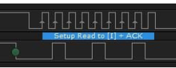
I found a problem SCL and SDA pulse which is made from I2C communciation.

It seems that SDA pulse is delayed. 

Actually I did interfacing very well with MCU from another company.

It might be pulse is generated like this below pic. 

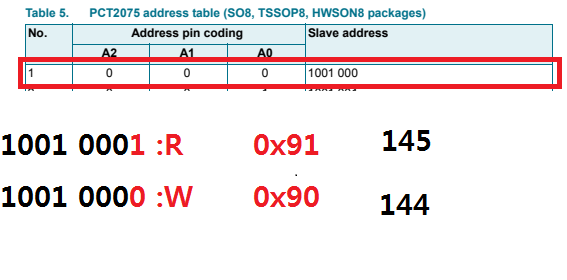
Slave address is 0x90(1001000). 

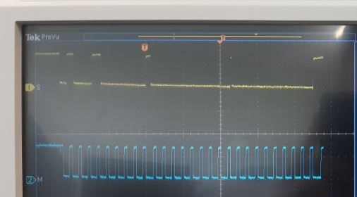
How to solve this problem?  How to align pulses?

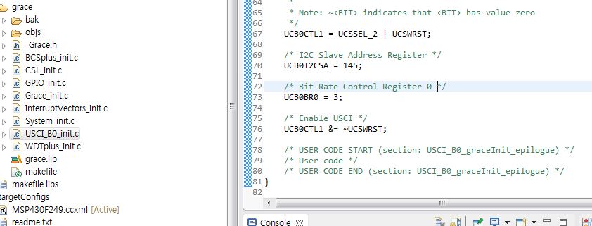
I used a code from MSP430ware (msp430x24x_uscib0_i2c_04.c)

  • I wrote a code like below
    //main.c
    int main(void) { Grace_init(); // Activate Grace-generated configuration while(1) { while (UCB0CTL1 & UCTXSTP); // Ensure stop condition got sent UCB0CTL1 |= UCTXSTT; // I2C start condition while (UCB0CTL1 & UCTXSTT); // Start condition sent? UCB0CTL1 |= UCTXSTP; // I2C stop condition __bis_SR_register(CPUOFF + GIE); // Enter LPM0 w/ interrupts } // >>>>> Fill-in user code here <<<<< }

    #pragma vector=USCIAB0TX_VECTOR
    __interrupt void USCI0TX_ISR_HOOK(void)
    {
        /* USER CODE START (section: USCI0TX_ISR_HOOK) */
    	RXData = UCB0RXBUF;                       // Get RX data
        __bic_SR_register_on_exit(CPUOFF);        // Exit LPM0
        /* USER CODE END (section: USCI0TX_ISR_HOOK) */
    }
    

  • Hi,

    I don't get your point. 

    What do you mean that SDA pulse is delayed?

    Besides, you show a problem picture. Do you mean this part is wrong?

    Eason

  • Right. Is it right when I coded the slave address as 0x91 or 0x90?

  • Strictly speaking your slave address (assuming A0-A2=GND) is 0x48 (0b01001000), and that's what should be stored in the I2CSA register. Where is the code where you set this?

    Curiously enough, address 0x24 appears to be working, though I don't see that choice in PCT2075 data sheet Table 5.

  • You use a 7bit address mode, actually you want to use a 10bit address mode. Please double check your code.

    Eason

  • I used a 7 bit address mode. becuase this sensor use a 7 bit address mode.

    so I used a slave address as 0x91 for reading.

    I don't know why pulse show like it.

  • I set a slave address with Grace and check it. 0x91(145)

    Isn't it right? I don't know why pulse show like that

  • Hi,

    if you want to use 7 bit address mode.

    0x90 = 0b1001 0000

    You see, you can't save 0x90 into a 7 bit address. Seeing from you second picture, your address should be 0x48 (0b01001000)

    Eason

**Attention** This is a public forum