This thread has been locked.

If you have a related question, please click the "Ask a related question" button in the top right corner. The newly created question will be automatically linked to this question.

MSP432P4111: MSP432 power draw too high

Part Number: MSP432P4111

We've ported an MSP430 based application to the MSP432 and we're having an issue with power consumption on the MSP432, despite using LPM3 in our idle task, as we did on the MSP430.  The code is almost identical between the two platforms, with obvious differences between the driverlib APIs.  Both processors have similar peripherals, and both are running at 8 MHz.  All pins are properly terminated or set to output low to minimize power.

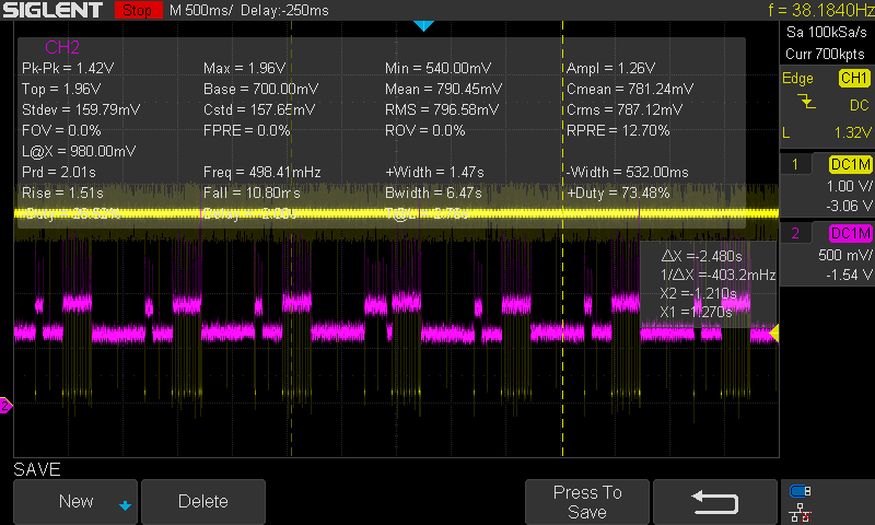
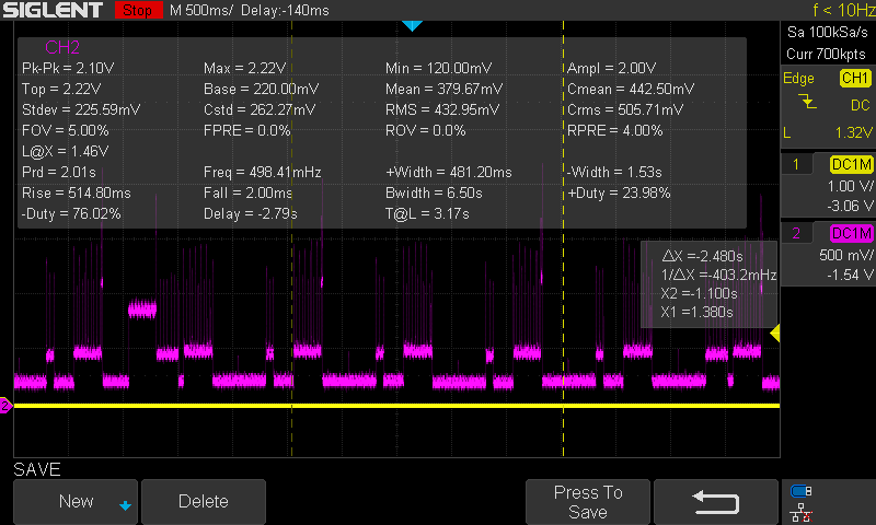
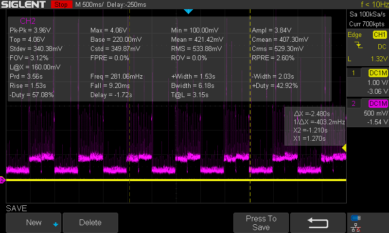
The two traces below show the comparison in power draw in real time, where the MSP432 draws approximately 1.44 mA, while the MSP430 draws approximately 0.84 mA.  The stepped up higher levels represent the power draw of the sensors, which are turned on and off.

We were under the impression that the MSP432 would draw comparable or less current than the MSP430 did, but this shows an increase of 0.6 mA, which is a show stopper for our low power requirements.  If we can't get the power down we may be dead in the water.

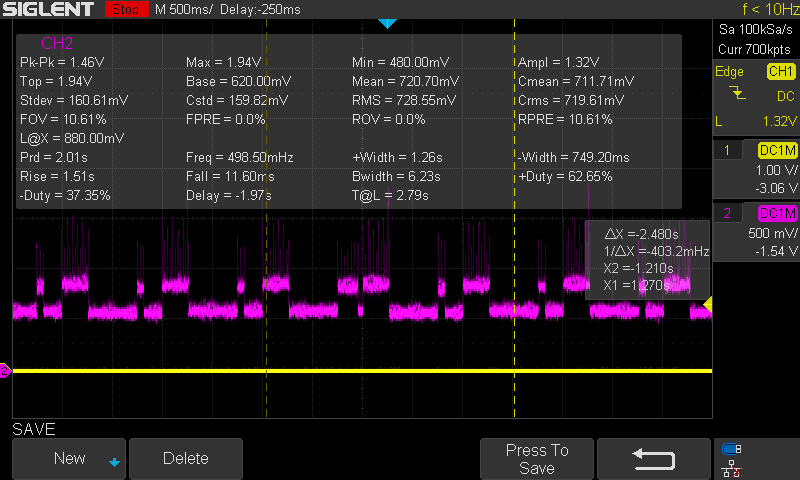
We have our own task scheduler which puts the system into LPM3 mode when idle until an interrupt occurs, at which point the system goes back into active mode, services the interrupt, then whatever task is associated with the event that caused the interrupt, then goes back into LPM3.  A GPIO output pin was used to monitor the relative time the system is in LPM3, which is probably around 99%.

There was a difference of around 0.7 mA if I removed the call to go to LPM3, so it looks like LPM3 is working.

Any ideas on why the MSP432 is drawing so much more current than the MSP430?  It seems like if we could get the lower level of the trace on the MSP432 to match that of the MSP430, we would be good to go.

Thanks.

MSP432 Power Draw

MSP430 Power Draw

  • Hello,

    In order to try and determine the root cause of the issue I would like to try and learn a little bit more about your application. According to the device datasheet, active on-chip peripherals can have a substantial impact on the overall current consumption based on which peripheral groups are activated:

    Could you give me an overview of which peripherals are used in the application in order to see if the current you are measuring is higher than expected? Also, the screenshots you provided seem to be a voltage waveform over time. Are you measuring this using a resistor in series with the power supply pin? Are you able to measure current directly using a power analyzer instrument so that direct current draw can be plotted over time?

    Best regards,

    Matt

  • Unfortunately we are using peripherals from all three groups, and there's no way around that for our application, but we are systematically disabling peripherals in an attempt to narrow it down, and it looks like we're best off focusing on each group one at a time.

    The challenge is to find the source of the DC component bias that causes the MSP432 waveform to be higher than the MSP430, given that the peripherals and the software are almost identical between the two, but there are differences, so we're focusing on those differences.

    What you see in the scope trace appears to be a voltage waveform when in fact it's a current waveform, the output of a current sensor that's fed into the scope with a conversion factor from volts to amps.  At the moment I'm not as concerned about the absolute numbers as I am about the comparison between the MSP430 and the MSP432.  If we can get the MSP432 current profile to match that of the MSP430 we're good.  If not, this effort to migrate from the MSP430 to the MSP432 may be a waste of time.

    The waveforms below show the on-time of LPM3 mode and a transition from LPM3 to give you an appreciation for how much time we're spending in LPM3, and the effect switching out of LPM3 has on the current.

    LPM3 On-Time (yellow trace)

    LPM3 transition showing the effect of momentarily disabling LPM3

  • Your method of current consumption monitoring makes sense now, thanks for the explanation. Just out of curiosity, what is the conversion factor between Volts to Amps on your scope shots?

    What MSP430 device are you basing your current consumption comparisons off of? I am not exactly sure which IP is shared between the two devices and it may be the case that the technology/IP is different which will result in a different current consumption profile for each device, even if the same modules and power modes are used in both cases. It may help to go through the datasheet to see the current consumption for each IP used to see if what you are measuring is expected or not based upon your operating voltage and peripheral configuration.

    Best regards,

    Matt

  • The ratio is two to one, so 1 mV = 2 mA.  The last two plots seem high for some reason, but generally I'm getting somewhere in the neighborhood of 720 mV = 1.44 mA for a mean current draw on the MSP432, compared to 421 mV = 842 mA on the MSP430.  The difference in current draw is almost equal to the difference we're seeing if LPM3 is disabled, which is around 0.7 mA.

    The variant of the MSP430 we were using is the MSP430F5438A.

    At the moment the code we're running on the MSP432 is almost identical to the MSP430, so no new IP yet.  Our immediate goal is to provide identical functionality to the MSP430, with the understanding that the MSP432 is computationally more powerful and will provide us a better path forward for future development.  All of the functionality seems to be in place, now we just need to get the power down.

    First we need to prove that the MSP432 platform can do what the MSP430 platform can do, then we move forward from there.  The plan is to add some computations to transform what is now a sensor into an instrument with more capabilities that does analysis in addition to monitoring.

  • I tried substituting the call to PCM_gotoLPM3() with a call to PCM_gotoLPM0(), because I understand there may be conditions where the transition to LPM3 may not be possible.  The results were telling in the sense that the power draw was the same, if not a little lower, than LPM3.

    Any ideas of what to look for?

    Thanks.

  • There are device specific ways to properly configure the MCU to go into various LPM states which must be considered. There are code examples in the TI Resource Explorer which show how to properly enter LPM3 and other low power modes. Is your project based on one of the code examples? If not, it may help to take a look at them to see if your application is executing the same steps.

    Are you using a Launchpad or a custom board? If you are using a Launchpad then there may be other components on board that are impacting the current consumption.

    -Matt

  • We are using a custom board running at 8 MHz, switching between PCM_AM_LDO_VCORE0 and LPM3, assuming we're actually making it into LPM3, which I think we're not.  I'm not sure how to verify which mode we're in, because we lose emulation capabilities when in LPM.

    When I enable rude mode I get a comparable power profile to the MSP430, as shown below, which shows a mean current draw of 0.76 mA, so this is telling.  There are occasional high current levels as shown in the left side of the waveform, so I will try to identify the cause and eliminate it.

    We may look into an RTOS implementation to take advantage of the power management capabilities, but for now we need to deliver.

  • Thank you for the detailed info during this support process. I have contacted an expert in how the power modes of the MSP432 portfolio work and they explained what you are experiencing.

    As I depicted in a previous post, the peripherals on board are organized into Peripheral Groups (PG1, PG2, & PG3). If any peripheral in a single group is activated, that entire group is activated. This is why it is recommended, when feasible, to use peripherals in the same group when in low power mode. Your power analysis for the MSP430 solution is different because the power management unit in that portfolio of devices is a little different in the fact that you can individually activate certain peripherals in low power modes without affecting the power draw of other peripherals.

    I fully understand your reasoning behind wanting to move to the MSP432 platform in order to have the option to use the higher processing capabilities for your company's future products but if this power consumption issue does not meet your requirements then it may be best for you to stick to the MSP430 based solution for now because we are currently in the process of defining/executing an MSP MCU based roadmap that will address your higher processing capability needs while also keeping low power and cost as priorities.

    Best regards,

    Matt

  • We seem to have found the smoking gun, but it doesn't make sense.  It seems that if we configure our UART clock sources to be EUSCI_A_UART_CLOCKSOURCE_ACLK instead of EUSCI_A_UART_CLOCKSOURCE_SMCLK we can get the power to go down, but this constrains us to a maximum baud rate of 9600, which is too low for our application.  in other words:

    eUSCI_UART_ConfigV1 param.selectClockSource= EUSCI_A_UART_CLOCKSOURCE_ACLK;  //consumes 680uA of current

    versus

    eUSCI_UART_ConfigV1 param.selectClockSource= EUSCI_A_UART_CLOCKSOURCE_SMCLK;  //consumes 1.4mA of current

    This is unexpected, because our SPI ports are sourced by SMCLK, and that doesn't prevent us from going into LPM3, so:

    eUSCI_SPI_MasterConfig param.selectClockSource = EUSCI_B_SPI_CLOCKSOURCE_SMCLK;  //goes into LPM3

    I am in the process of trying to generate an example based on one of the examples you provide to demonstrate this.

  • While you work on putting together a simplified example demonstrating this current consumption difference, could you please let me know what you are using to source ACLK in your application?

    -Matt

  • ACLK is sourced by an external high precision oscillator at 32,768Hz:

    CS_initClockSignal(CS_ACLK, CS_REFOCLK_SELECT, CS_CLOCK_DIVIDER_1);

    CS_startLFXT(CS_LFXT_BYPASS); // set LFXTBYPASS bit to use external clock source

    Our DCO clock (SMCLK source) is set at 8 MHz, and our core voltage is set to PCM_VCORE0.

  • Hello,

    The UART in MSP432 doesn’t have start-edge detection to wake-up from LPMx like the MSP430. Newer ARM processors have implemented dedicated LP-UART modules, or some workarounds to be able to wake-up the UART because of this.

    When you enabled rude mode (disabled high-speed bus requests), the UART (which was requesting the bus) got disabled thus explaining the lower current consumption.

    One workaround for the UART you can try is using a GPIO to wake-up the device from LPMx and then doing the UART communication.

    Best regards,

    Matt

  • Thanks for the explanation.  We came to that conclusion as well that the UART wasn't waking up from LPM3 fast enough to service the interrupt.  We will try your workaround, which should work, because our application will permit lost packets while the port wakes up and configures itself to a higher baud rate.

    We were able to make the power go down to the original low level (680 uA) by clearing the Rx interrupt flag, disabling the interrupt, and disabling the UART prior to re-configuring it with ACLK as the source.

    I've tried to construct a simple example to demonstrate the difference in power draw related to the clock source, but my example was unable to prove the phenomenon we're seeing with SMCLK mapped as the clock source consuming higher power than with ACLK mapped as the clock source.  When I run my simple example the power draws are comparable.

  • I'm glad you were able to narrow down the source of the issue and have a plan to address it moving forward. If you happen to find any other workarounds or fixes please feel free to comment back on here so that others seeing the same problem can find a solution.

    Best regards,

    Matt

**Attention** This is a public forum