Part Number: MSP430FR2355
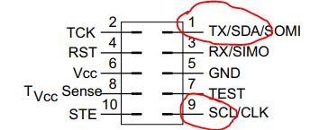
I am trying to program MSP430FR2355 using UART BSL through the BSL rocket/scripter. But it gives [ACK_ERROR_MESSAGE]Unknown ACK value! Attached my files. Please let me know where I am going wrong. Also if I want to use I2C BSL, do i need to have pull up resistors for the SCL, SDA lines? The launchpad for MSP430FR2355 does not seem to have them. Thanks!
//
//Script example FRxx UART BSL
//
//Device : MSP430FR2355
//Comm Bridge: MSP-BSL Rocket
//
//Download blink application through
//UART BSL in FRAM device
//
LOG
MODE FRxx UART 9600 COM22
//gives wrong password to do mass erase
RX_PASSWORD pass32_wrong.txt
//
//add delay after giving wrong password
//because the device does not give
//any response after wrong password applied
//
DELAY 2000
RX_PASSWORD pass32_default.txt
RX_DATA_BLOCK BlinkLED2355.txt
CRC_CHECK 0x4400 0x0020
SET_PC 0x4400
@8000
31 80 06 00 3E 40 00 00 3E F0 3F 00 81 4E 00 00
3F 40 01 00 1F F3 81 4F 02 00 3D 40 01 00 1D F3
81 4D 04 00 5E 06 5F 02 0F DE 1F D1 04 00 3F D0
00 A5 82 4F 60 01 31 50 06 00 10 01 B2 40 80 5A
CC 01 D2 C3 02 02 D2 D3 04 02 92 C3 30 01 D2 E3
02 02 0D 14 3D 40 32 82 1D 83 FE 23 0D 16 F7 3F
03 43 03 43 FF 3F 03 43 1C 43 10 01 31 40 00 30
B0 13 00 80 B0 13 68 80 0C 43 B0 13 3C 80 1C 43
B0 13 62 80 32 D0 10 00 FD 3F 03 43
@ff80
FF FF FF FF FF FF FF FF FF FF FF FF
@ffa0
FF FF
@ffce
84 80 84 80 84 80 84 80 84 80 84 80 84 80 84 80
84 80 84 80 84 80 84 80 84 80 84 80 84 80 84 80
84 80 84 80 84 80 84 80 84 80 84 80 84 80 84 80
6C 80
q