This thread has been locked.

If you have a related question, please click the "Ask a related question" button in the top right corner. The newly created question will be automatically linked to this question.

MSP430F5529: MSP430F5529 one ADC channel interfere with another channel issue

Part Number: MSP430F5529

Hello  TI Team / Forum experts,

Can you please help me in the following case.

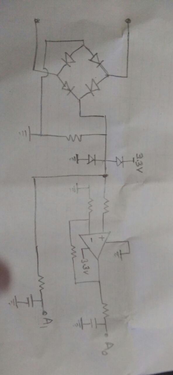
In my design , I am using MSP430 adc channels A0 , A1 , A2 , A3 & A13. A0 to A3 for ac current measurement and A13 measures a DC signal ( Max 2.5 V dc ).

Following are few brief setting information for adc application code :

  1. ADC12_A conversion sequence mode is Sequence-of-channels.
  2. Software-controlled sample-and-conversion start.
  3. Reference is internal 2.5V
  4. ADC12_A sample-and-hold time = 4 ADC12CLK cycles

Voltage to A13 channel is 2.5 in default case.

What we find that A0 channel (ADC12MEM0) reads adc count value significant enough to disturb our application even though no current is injected. Just to troubleshoot, if we reduce the signal to A13 to zero ( forcefully connecting A13 pin P7.1 to GND signal ) , the adc count reading from A0 channel disappears or reads 1 / 2 count. But we can not make channel A13 to zero as this signal is dependent on a sensor ( 0 to 2.5 V dc ).


  1. Can you please provide a FIRMWARE solution for the above  case. i.e how to minimize the effect on channel A0 from A13.
  2.  My application uses A0 , A1 , A2 , A3 and A13. Does it means that the sample and conversion time counts for those selected channels only or time will be calculated considering A0 to A13 i.e total 14 channels.

    ADC12MCTL0 = ADC12SREF_1+ADC12INCH_0;        

    ADC12MCTL1 = ADC12SREF_1+ADC12INCH_1;

    ADC12MCTL2 = ADC12SREF_1+ADC12INCH_2;        

    ADC12MCTL3 = ADC12SREF_1+ADC12INCH_3;

    ADC12MCTL13 = ADC12SREF_1+ADC12INCH_13+ADC12EOS;


rgds/

Ars


  • 4 clocks for sample/hold is pretty short. Too-short sample/hold (inability to settle the sampling capacitor) can masquerade as channel crosstalk. 

    Have you checked your S/H time against your sensors' input impedances using the formula in User Guide (SLAU208Q) Sec 28.2.5.3?

  • Thanks for your valuable points.

    Bruce McKenney47378 said:

    4 clocks for sample/hold is pretty short. Too-short sample/hold (inability to settle the sampling capacitor) can masquerade as channel crosstalk. 

    Ok. i will check increasing it. But with same no adc clk cycles others channels A1 to A3 are ok.results are fine.

    My thought is that after sample/conversion of A13 adc again starts with channel A0.may be at the time of switching A0 , internal sample and hold capacitor was not able to discharged properly from A13 state.

    Bruce McKenney47378 said:
    Have you checked your S/H time against your sensors' input impedances using the formula in User Guide (SLAU208Q) Sec 28.2.5.3?

    All the ADC channels are connected to Op-Amp output.sensors are interfaced to adc via opamp.so i guess sensor's input impedance shouldn't be a problem for MSP430 ADC looking at  Sec 28.2.5.3.

    Rgds/

    Ars


  • Ars said:
     My application uses A0 , A1 , A2 , A3 and A13. Does it means that the sample and conversion time counts for those selected channels only or time will be calculated considering A0 to A13 i.e total 14 channels.

    ADC12MCTL0 = ADC12SREF_1+ADC12INCH_0;        

    ADC12MCTL1 = ADC12SREF_1+ADC12INCH_1;

    ADC12MCTL2 = ADC12SREF_1+ADC12INCH_2;        

    ADC12MCTL3 = ADC12SREF_1+ADC12INCH_3;

    ADC12MCTL13 = ADC12SREF_1+ADC12INCH_13+ADC12EOS;

    Can TI team or forum plz help with the information ? if it is for those selected channels only ....then i can try increasing no of adc clock cycles for sample/hold time. else if it is for 14 channels then timing is critical for the application.....because of following :

    My design uses a timer interrupt of around 135 uSec....for complete application control including a data logging.And ADC is triggered from that interrupt routine only.

    so with 4 adc clock cycles....5 adc channel adc data will take around 35 usec ( Sample + Conversion Time )....and  

    with 8 adc clock cycles....5 adc channel adc data will take around 44 usec ( Sample + Conversion Time ).....whereas  if it's 14 channel to be considered then

    adc data will take around 122 usec ( Sample + Conversion Time )......which is very close to my global  timer interrupt .

    Regards,

    Ars

  • Bruce McKenney47378 said:

    4 clocks for sample/hold is pretty short. Too-short sample/hold (inability to settle the sampling capacitor) can masquerade as channel crosstalk. 

    Have you checked your S/H time against your sensors' input impedances using the formula in User Guide (SLAU208Q) Sec 28.2.5.3?

    Yes. Bruce I have checked.

    As i said....My sensor circuit is interfaced to MSP430 ADC via a op-amp and R-C filer connected between op-amp and adc channel is 1K Ohm and 100nF.

    so for 12 bit resolution , by using formula from User Guide (SLAU208Q) Sec 28.2.5.3 , my design requires 1.43 uSec for each channel theoretically.....whereas with 4 ADC clock cycles i get approx 1.66 uSec of sample and hold time for each channel.

    Any other method plz that i can try to minimize the adc channel interference.surprisingly in my case Channel A13 not affecting channels A1, A2 ,A3 much .They read  just 3 or 4 adc counts.

    Regards,

    Ars

  • OK. I mentioned the formula it since sometimes people (like me) forget, and that's the symptom I, uh, they see.

    The ADC12OSC usually runs about 5MHz, which would be a <1usec S/H. Or are you dividing it?

    Sorry, I missed question (2) before: The S/H time applies to each conversion in the sequence.

    Are you interested in 5 channels or 14 channels? If EOS is at MCTL13, you're converting 14 channels, so if you only need 5 that's unnecessary work/time. You can set "ADC12MCTL4 = ADC12SREF_1+ADC12INCH_13+ADC12EOS;" if you want.

    [Edit: Fixed some typos]

  • Hello Bruce,

    Thanks for your Help.

    Bruce McKenney47378 said:
    The ADC12OSC usually runs about 5MHz, which would be a <1usec S/H. Or are you dividing it?

    ADC clock runs in my design at 2.4 MHz ( derived from SMCLK and diving it down )..There is an errata for this part on adc ( errata no : ADC27) which says  about a workaround to get ADC12_A integral and differential non-linearity within limit ,  adc clock frequency should be < 2.7 MHz

    Errata msp430f5529_slaz314ac.pdf

    Bruce McKenney47378 said:
    Are you interested in 5 channels or 14 channels? If EOS is at MCTL13, you're converting 14 channels, so if you only need 5 that's unnecessary work/time. You can set "ADC12MCTL4 = ADC12SREF_1+ADC12INCH_13+ADC12EOS;" if you want.

    I want to use 5 channels i.e A0 , A1 , A2 , A3  and A13 only.But thought i need to use  ADC12MCTL13 for Channel A13 and in that case 14 channels will be sampled and converted whether i use or not.

    But you have well clarified it here. Now i can do like this to get the sample/conversion time involving  those 5  adc channels only.

    ADC12MCTL0 = ADC12SREF_1+ADC12INCH_0;  // ADC12MEM0

    ADC12MCTL1 = ADC12SREF_1+ADC12INCH_1;  // ADC12MEM1

    ADC12MCTL2 = ADC12SREF_1+ADC12INCH_2; // ADC12MEM2

    ADC12MCTL3 = ADC12SREF_1+ADC12INCH_3; // ADC12MEM3

    ADC12MCTL4 = ADC12SREF_1+ADC12INCH_13+ADC12EOS ; //  i.e ADC12MEM4 for channel A13

    with the above approach and increasing the sample and hold time to 8 ADC clock cycles helped me to reduce the interference on Channel A0 ( count reduced from 48 to around 24 ) but not removed completely.

    Any other suggestion plz.

    Regards/

    Ars

  • It seems odd that only channel A0 is affected. Is there something unique about that signal source?

    If all else fails, add a dummy channel to the end of the conversion list and tie that input to ground.

  • A fairly quick experiment would be to re-order the channels, e.g. swap the INCH settings for MCTL0/1 (and the code which reads MEM0/1) and see if the symptom moves with the channel.

    As I understand it, you're using CONSEQ=1 (and MSC=1) with a 135us timer trigger? I.e. there is a delay between reading the last channel and the first?

    Some months ago, another user reported a similar(-ish) symptom over here:

    https://e2e.ti.com/support/microcontrollers/msp430/f/166/t/895970

    though he had (1) ADC12_B rather than ADC12_A and (b) an R/C, rather than an opamp, feeding the ADC channel(s). Lixin had some concerns about the capacitance, though there was no resolution. But I thought I'd mention it.

  • Thanks David for your suggestions.

    David Schultz36 said:
    It seems odd that only channel A0 is affected. Is there something unique about that signal source?

    not really . A0 , A2 are high gain channel from similar sensor ckt  and A1,A3 low  gain. Please see the  current sensor bridge ckt to A0 / A1 adc channel in the pic. might help in understanding my issue.

    David Schultz36 said:
    If all else fails, add a dummy channel to the end of the conversion list and tie that input to ground.

    Yes , I have added a dummy channel.But no change in result. Unfortunately i can't tie that i/p to gnd ...as my hardware already installed in field.Only possibility is firmware update,

    rgds,

    Ars

  • Thanks ...Bruce give me a helping hand on this topic.

    Bruce McKenney47378 said:
    A fairly quick experiment would be to re-order the channels, e.g. swap the INCH settings for MCTL0/1 (and the code which reads MEM0/1) and see if the symptom moves with the channel.

    I tried re-ordering.But behaviour remains unchanged.

    Bruce McKenney47378 said:
    As I understand it, you're using CONSEQ=1 (and MSC=1) with a 135us timer trigger? I.e. there is a delay between reading the last channel and the first?

    You are correct .CONSEQ=1 (and MSC=1).There is no delay between reading the last channel and the first ,in my code. All channels are read(ADC12MEMx) once in a timer interrupt and then triggered for next sample/conversion.

    I have attached a pic of my ckt concept....in last post.

    Regds,

    Ars

  • With an RC filter on the inputs you need to be careful about values but you show none. With R large enough to cause sampling time problems then C needs to be large enough relative to the sampling capacitance so that after sampling redistributes charge, the change is less than 1/2lsb.

  • David Schultz36 said:
    With an RC filter on the inputs you need to be careful about values but you show none.

    R = 1K ohm , C = 100 nF

    David Schultz36 said:
    With R large enough to cause sampling time problems then C needs to be large enough relative to the sampling capacitance so that after sampling redistributes charge, the change is less than 1/2lsb

    OK

    regds

    Ars

  • Does "unchanged" mean the symptom followed A0, or stayed at MCTL0? Based on the answer to this you might want to put the "dummy" channel at the beginning rather than the end.

    By "delay" I just meant "a time gap between bursts", not necessarily a deliberate delay. I'm just trying to get a sense of the dynamics.

    Another experiment would be to turn the SHT up as high as you can manage within your time slot. With SHT=2 (16) my calculator says 5*(16+12+1)/2.5MHz=58usec, which seems enough less than 135usec to succeed. 

  • Bruce McKenney47378 said:
    Does "unchanged" mean the symptom followed A0, or stayed at MCTL0?

    Yes, It followed A0.

    Bruce McKenney47378 said:
    Based on the answer to this you might want to put the "dummy" channel at the beginning rather than the end.

    OK.I assume dummy at the end( i tried.....) or beginning will not change the result significantly logically .any way let me give a try.

    Bruce McKenney47378 said:
    Another experiment would be to turn the SHT up as high as you can manage within your time slot. With SHT=2 (16) my calculator says 5*(16+12+1)/2.5MHz=58usec, which seems enough less than 135usec to succeed.

    Actually I would  be adding 4 more channels. so max  SHT=1 ( 8 clock cycles) i can go for considering highest variant of my product design.

    Thank you group.

    Rgds,

    Ars

  • That the symptom moved with A0 really seems to suggest that it's something electrical, with just that port. The fact that it improved (even if it didn't go away) with a longer S/H time suggests something about input impedance.

    I didn't realize you were planning on adding 4 more channels. If we suppose A0 is the only problematic channel, here's another trick: Use MCTL7-15, starting with A0 in MCTL7, and set CSTARTADD=7. Set SHT0=(long) and SHT1=(shorter). This will use the longer S/H time only for A0.

  • Hi Ars,

    We haven’t heard from you for a couple of days now, so I’m assuming you were able to resolve your issue.
    If this isn’t the case, please click the "This did NOT resolve my issue" button and reply to this thread with more information.
    If this thread locks, please click the "Ask a related question" button and in the new thread describe the current status of your issue and any additional details you may have to assist us in helping to solve your issues.

  • Hello Bruce / David,

    Thanks for your valuable suggestions and help on the topic.

    Though we have done several experiments to remove the effect completely(however it reduces a bit ) from the particular channel in firmware,practically it did not solve.so only option i see is a track layout change in my product H/W design.

    Hence ..Dennis , you can mark this thread lock.in case if i come across any new result...i will follow the standard forum guidelines to open up issue related it.

    Thanks & Rgds,

    Ars

**Attention** This is a public forum