This thread has been locked.
If you have a related question, please click the "Ask a related question" button in the top right corner. The newly created question will be automatically linked to this question.
Tool/software: Code Composer Studio
Dear team,
Customers have tested SD24_B and found problems when using it.
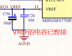
When the input voltage is 0, the result register still has a value, the 100nf capacitor has been connected, the code is modified on the official routine, the code is as follows.
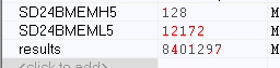
The customer uses channel 5. In order to eliminate interference, both the positive and negative terminals are connected to DGND, but there are still very large values, and the value in the SD24BMEML5 register has been changing。
#include <msp430.h> /* Unsigned integer to store SD24_B conversion result */ unsigned long results; void main(void) { WDTCTL = WDTPW | WDTHOLD; // Stop WDT SD24BCTL0 = SD24REFS | SD24SSEL_1; // Select internal REF // Select SMCLK as SD24_B clock source SD24BCCTL5 |= SD24SNGL; // Single conversion SD24BINCTL5 |= SD24INTDLY0; // Interrupt on 3rd sample SD24BIE |= SD24IE5; // Enable channel 2 interrupt __delay_cycles(0x3600); // Delay for 1.5V REF startup while (1) { SD24BCCTL5 |= SD24SC; // Set bit to start conversion __bis_SR_register(LPM0_bits | GIE); // Enter LPM0 w/ interrupts __no_operation(); __no_operation(); // SET BREAKPOINT HERE } } #if defined(__TI_COMPILER_VERSION__) || defined(__IAR_SYSTEMS_ICC__) #pragma vector=SD24B_VECTOR __interrupt void SD24BISR(void) #elif defined(__GNUC__) void __attribute__ ((interrupt(SD24B_VECTOR))) SD24BISR (void) #else #error Compiler not supported! #endif { switch (SD24BIV) { case SD24BIV_SD24OVIFG: // SD24MEM Overflow break; case SD24BIV_SD24TRGIFG: // SD24 Trigger IFG break; case SD24BIV_SD24IFG0: // SD24MEM0 IFG break; case SD24BIV_SD24IFG1: // SD24MEM1 IFG break; case SD24BIV_SD24IFG5: // SD24MEM2 IFG results = SD24BMEMH5; // Save CH2 results (clears IFG) results = (results << 16) | SD24BMEML5; // Concatenate lower and upper words break; default:break; } __bic_SR_register_on_exit(LPM0_bits); // Exit LPM0 }
Please help.
Hi, Susan,
It seems the code was modified based on the code example msp430f677xA_sd24b_06.c.
Original code is using channel 2. Your code is change 5.
Do you have set the breakpoint at the point mentioned in the code and use debugger to view the conversion result at the breakpoint?
If yes, the code should be no problem.
The GND should analog GND (AGND) if customer would like to connect the input channel 5 to GND. Could you check the DGND signals with oscilloscope?
In addition, can customer repeat the test in TI demo board or target socket board? This is to find the difference between the boards.
Thanks,
Lixin
Hello, teacher! Today, I tested again, using the reverse voltage signal to access the channel, and found that the value of results is approximately 0 when the voltage of about 1V is input in reverse. I wonder if you have seen this situation before.?
No. I didn't see this before.
Could you compare the test result between your board and TI evaluation board?
And could you also change the channel from 5 to channel 2 to see if there is different result?
Hello, teacher! Thank you for your reply!
I'm sorry that I only have the circuit board soldered by myself, and I use the MCU of MSP430F6779. I tried to change the channel, but the result is still the same. In addition, I tested ADC10 of the chip, and the result was good, that is, SD24 did not perform well.
Hi,
I double checked your conversion result. It is reasonable data.
The SD24BMEMH5 is 128 which is 0x80 in Hex. That means almost 0V for differential input.
The SD24BMEML5 is 12172. For VID input voltage range +/-930mV, the conversion result voltage is about 1.349mV. I think it is reasonable value since there is ground noise on the board. (Conversion result 0x00FFFFFF means greater than maximum VID, and 0x00000000 means less than minimum VID)
My test result on TI evaluation board is about 0x00800F25. It is about 0.46mV for VID input voltage range +/-930mV.
The VID can be set by register SD24GAINx registers. Please refer to datasheet and user's guide for details.
Thanks,
Lixin
Hi,
I think you have understood the SD24 result data format, right?
Do you have any other questions?
Thanks,
Lixin
**Attention** This is a public forum