This thread has been locked.

If you have a related question, please click the "Ask a related question" button in the top right corner. The newly created question will be automatically linked to this question.

MSP430FR2422: LED Blink Try using ISR

Part Number: MSP430FR2422

Hi ,

I am trying to blink the LED on my custom board present on the P1.1 and my interrupt pin is P2.2 . SO my main aim is to turn on the led and keep on until the interrupt is there. Also i am manually giving P2.2 the +5V signal when i want to check for interrupt .

LED   ->    P1.1

Interrupt Pin   ->  P1.2

This code is NOT showing error .But somehow this is not working, can you please help me in this problem.

Here is my code which i have tried


#include "driverlib.h"
#include <msp430.h>
void main(void) {

WDT_A_hold(WDT_A_BASE);
PMM_unlockLPM5();

//FRCTL0 = FRCTLPW | NWAITS_1;

//CS_setExternalClockSource(XT1CLK_frequency)(CS_DCORSEL_1, CS_DCOFSEL_4);

// Configure the clock time as the interrupt should be called on the interrupt call .
// The CS ACLK is for clk and vloclk will be for vlo and by default cs clock divider will be 1
// The MCLK is for other mclk and I had done the optional thing .

CS_initClockSignal(CS_ACLK, CS_VLOCLK_SELECT, CS_CLOCK_DIVIDER_1);
CS_initClockSignal(CS_MCLK, CS_VLOCLK_SELECT, CS_CLOCK_DIVIDER_1);

// Set P1.1 as the output and P1.2 as the interrupt pin
GPIO_setAsInputPin(GPIO_PORT_P1, GPIO_PIN1);
// First disable the Interrupt and then after that enable it
GPIO_disableInterrupt(GPIO_PORT_P1, GPIO_PIN2);

// clears all the interrupt flag if there are initially there
GPIO_clearInterrupt(GPIO_PORT_P1, GPIO_PIN2);

//at what time you want to have the interrupt that means on positive edge or negative edge

GPIO_selectInterruptEdge(GPIO_PORT_P1, GPIO_PIN2, GPIO_LOW_TO_HIGH_TRANSITION);
GPIO_enableInterrupt(GPIO_PORT_P1, GPIO_PIN2); // Here the interrupt is enabled
__enable_interrupt(); // enables the interrupt


while(1)
{

}
}
// Now from here the interrupt service routine starts in which the interrupt to do task is done yet it does not toggle the led we want due to some power advice

#pragma vector = PORT1_VECTOR;
__interrupt void Port_1 (void)
{
GPIO_toggleOutputOnPin(GPIO_PORT_P1, GPIO_PIN1);
GPIO_clearInterrupt(GPIO_PORT_P1, GPIO_PIN2);
// If we did not clear the interrrupt than if the power is off on the corresponding switch then also it will stay in the interrupt irrespective of the change
}

  • // Set P1.1 as the output and P1.2 as the interrupt pin
    GPIO_setAsInputPin(GPIO_PORT_P1, GPIO_PIN1);

    That code sets P1.1 as in input put, not an output pin. Try:

    // Set P1.1 as the output and P1.2 as the interrupt pin
    GPIO_setAsOutputPin(GPIO_PORT_P1, GPIO_PIN1);

    Also i am manually giving P2.2 the +5V signal when i want to check for interrupt .

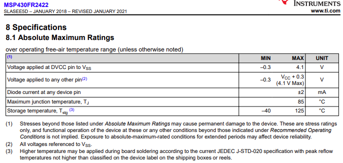
    Applying +5V to a pin exceeds the absolute maximum ratings of the device, and could lead to damage:

    Is there a series resistor between the +5V signal and P2.2 to limit the protection diode current to less than 2mA?

    See Interfacing (safely) with the MSP430 and ESD Diode Current Specification for some background information.

  • 1) How is your button wired? In particular (a) do you have an external pullup or pulldown resistor? (b) what pin is it connected to (you mentioned both P1.2 and P2.2)?

    2)

    > GPIO_setAsInputPin(GPIO_PORT_P1, GPIO_PIN1);

    Unless you have an external pullup/down resistor (and maybe even if you do) you should use the internal pullup/down, something like:

    > GPIO_setAsInputPinWithPullUpResistor(GPIO_PORT_P1, GPIO_PIN2); // P1.2 button as input/pullup

    3) To use the LED you need to configure its pin as an output:

    > GPIO_setAsOutputPin(GPIO_PORT_P1, GPIO_PIN1);         // P1.1 LED as output

    > GPIO_setOutputLowOnPin(GPIO_PORT_P1, GPIO_PIN1);  // Initially off (active high)

    4) 

    > #pragma vector = PORT1_VECTOR;

    Remove that semicolon at the end. I'm not quite sure what the preprocessor will do with it, but it doesn't belong.

    ----------------------

    There's an Example (gpio_ex2_inputCapture), similar to what you're trying to do, over here:

    http://dev.ti.com/tirex/explore/node?node=AFK0MVH-fBllg.vv1-P17g__IOGqZri__LATEST

  • Thanks Chester, this resolved my issue. I mistakenly took the input and I was only finding the fault in the ISR. 

**Attention** This is a public forum