This thread has been locked.

If you have a related question, please click the "Ask a related question" button in the top right corner. The newly created question will be automatically linked to this question.

MSP430 CDC example running problem

Other Parts Discussed in Thread: MSP430F5510

Hi,

I'm trying to run example application for USB communication. 12 MHz crystal is used as XT2 oscillator. I copied C1_Eample folder form TI USB Developers Pack. I changed device to MSP430f5510, USB_MCLK_FREQ to 12000000 and USB_XT_FREQ to USBPLL_SETCLK_12_0.

Building all, debuging, running.

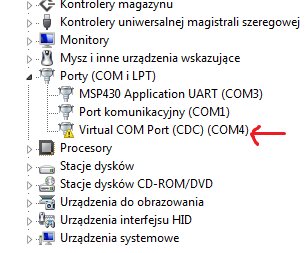
When I connect usb port to PC, Windows (7, x64) the device manager shows "Unknow Device". After checking its proporties I see something like this (this is not my picture, but device status is the same):

After uninstalling existing drivers and installing new ones choosing folder with .inf file I have (now it is my screen):

In proporties I can see Code 10 error. Of course there isn' t COM4 in terminal.

Directly choosing .inf file as an installation file occurs message the file isn't proper for this system, but if we open .inf file in Wordpad we can see section: for Windows x64.

Maybe isn't it supported by Windows 7?

Has anyone any idea what is wrong?

Regards,

Mikolaj

  • Hi Mikolaj,

    It looks like your device has trouble being enumerated. Have you tried breaking the program right after Windows complains of "Unknown Device" and see where the code execution is?

    There is an errata for the MSP430F5510 LDO where sometimes the device can fail to detect the 5V VBUS; unfortunately the "fix" in the USB package involves cycling the LDO, which is catastrophic for bus-powered devices relying on the LDO as it means an endless reset loop. If this is the case try commenting out USBPWRCTL = 0; in USB_Init().

    Also check to see if you have the proper line impedance matching (90ohms, which is 45ohms differential D+/D-, minus parasitics), and the right pull-up resistor (~1.5K from PUR to D+).

    Finally it goes without saying that you have to be very, very careful mucking about with the 5V rail near the MSP430, since the only 5V tolerant pins are D+, D-, and VBUS. A short to any other pins will likely cause the device to fail catastrophically.

    Hope this helps :)

    Tony

  • TonyKao said:

    There is an errata for the MSP430F5510 LDO where sometimes the device can fail to detect the 5V VBUS; unfortunately the "fix" in the USB package involves cycling the LDO, which is catastrophic for bus-powered devices relying on the LDO as it means an endless reset loop. If this is the case try commenting out USBPWRCTL = 0; in USB_Init().

    Wow! You are awesome! Thank you very much for this info. It helps!

    I have read all API USB Programming Guide and I haven't seen any info about it.

    Best regards!

  • @TonyKao:

    We have used MSP430F5510 as the core for one of our projects. It is continuously powered by a CR2450 coin cell, but uses USB power instead of cell's when available.

    Your statement about this chip LDO errata is keeping me breathless. We have the application in preproduction phase and, even if it has never shown any problem to get enumerated by WIndows, no matter what flavor of  Windows your system uses, it has started to show such inability to get enumerated in our customer factory.

    We have prepared several working units for them to use and have around if any checking / benchmarking is needed. However, even though those units where properly and thoroughly tested in our lab, our customer seems to be unable to get them enumerating on Windows. Is it possible that ALL of the units (proven to work in our PC systems) might be unable to get enumerated in their system?

    In case it is, do you think it is reasonable to trace the problem to this so-called errata in MSP430F5510 LDO? For ALL the units?

    Of course, I can comment "USBPWRCTL=0;" line in "USB_Init()", but I would like to base that move in something steadier than a "sometimes".

    Please, let us know your appreciated point of view.

    Kind regards.

    Antonio Rodulfo, R&D Engineer

  • Hi Antonio,

    Something that you may want to try: Immediately after USBPWRCTL=0, set the VUSBEN bit in the register, i.e.

    USBPWRCTL=0;

    USBPWRCTL |= VUSBEN;

    If your VUSB is properly bypassed, this should prevent the voltage from falling below brownout threshold, at the same time satisfying the USB9 errata.

    Also, if you had connected the debugger to the test units, this problem may fail to show up as the debugger would then supply the necessary voltage on DVCC.

    Tony

  • Actually, it just occurred to me that a better way to do this would be to test for USBBGVBV, and if it's missing (as per USB9) then the firmware clears USBPWRCTL.

    So

    if (USBPWRCTL & USBBGVBV)

    USBPWRCTL = 0;

    may do the trick.

    Tony

**Attention** This is a public forum