This thread has been locked.

If you have a related question, please click the "Ask a related question" button in the top right corner. The newly created question will be automatically linked to this question.

PCB connection of JTAG programmer

Other Parts Discussed in Thread: MSP430G2553, MSP430F5437A

Hi,

I need to make a pcb with a connector to support jtag programming.

I have seen the slau278i and this site ( http://processors.wiki.ti.com/index.php/JTAG_(MSP430) ) in order to see the connection for spy-bi-wire.

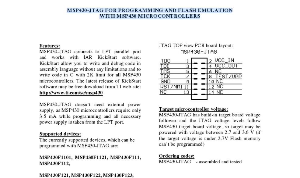
In order to know how to make the board (pcb) i have followed the top view from the photo i have attached...

Clearly, the top view differs from the schematic view... Is that right?

How the top view of the layout should be?

Thanks!

  • Leonardo Mart��nez said:
    ion for spy-bi-wire

    Your picture is showing a normal JTAG connection , there is a slight difference of signals you will need for JTAG and SBW ( spy by wire).

    JTAG uses more signals than SBW, basically they act the same, you are able to program and debug your MSP device. SBW is a little slower though.

    At least that is what I was expiriencing and I did program with both types and did also realize both types on my PCB designs.

    And then you are free to configure your signals to any PCB connector you want but the signals of course have to end in the certain associated pins from your MSP430. And I suppose you are using the MSP FET430UIF debugger/programer? because with this you can directly connect a 14 pole flat cable the way you already printed.

    Hope that gives you some more insight to what you are doing.

  • Yes, i will use a msp Fet430UIF...

    So you are saying that the top view of the picture is ok? 

    I will use that SBW connection for my msp430g2553 but i don't know if i am doing the right connection in the board (top view)...

    Thanks!

  • The 4-wire JTAG is commonly seen with the 14-pin male header. The 2 wire JTAG is also know as Spy-Bi-Wire interface which only requires SBWTDIO, SBWTCK, GND, and VCC to program. The following images were taken from CCE and IAR User's Guide (SLAU138 and SLAU157. Please refer to those documents for updated information.

    Then you are reffering to the wrong picture, it is also printed the one that uses less signals is SBW, now you have to connect the signals from the PCB header to your MSP and it should be working.

  • Hi seb,

    Where are the "following" images?

    Is my pcb header top view ok?

    Which is the right one?

    Thanks!

  • In my MSP430 SBW design i did use 2 signals ( thats why its calles 2 wire bus) TDIO and TDCK, your header is showing the JTAG connection.

    You must  know what you want to use if you wanna use JTAG on your MSP430 and your PCB header than it will work.

    If you want to use SBW on MSP430 and on the PCB header, then you will have to choose different signl routing ( of course you can use the same PCB header, because it is only  a mechanical component )

    Here the connection for SBW ( 2 wire)

    http://e2e.ti.com/resized-image.ashx/__size/550x0/__key/CommunityServer-Discussions-Components-Files/166/7506.SBW.png

    hope this helps.

  • Hi,

    Yes, i have the picture as a reference of the pin out of the MSPFET430UIF... I am gonna use the schematic you gave as reference for the connections. I will only use the pins related to SBW!

    My problem was what was the real connection in the board related to the connector i will use... By the way, i will use a smd 10 pin connector because i just need 5 pins which are located in the 10 pins of the top...

    From what you told me, i guess i was right...

    Thanks!

  • I was just looking for an explanation my msp430f5437a in the datasheet page 16  there is a good overview of the possible JTAG SBW or BSL connectinos an the associated pins.

    Unfortunatly I couldnt find this in your devices datasheet, perhaps you should contact TI, or look thourgh the Port sections, there it is explained for each pin to be put into JTAG mode.

    good luck and good weekend

  • Thanks, for your answers! Nice weekend!

  • I think that the SBW connections to the MSP-FET430UIF programmer differ from Olimex USB programmer:
      >> http://e2e.ti.com/resized-image.ashx/__size/550x0/__key/CommunityServer-Discussions-Components-Files/166/7506.SBW.png
      >> https://www.olimex.com/Products/MSP430/JTAG/_resources/SPY-BI-WIRE-CONNECTION.jpg

    Unfortunately parallel port JTAG doesn't support Spy-Bi-Wire devices as timing from parallel port can't meet programming specs.
    What is the difference between MSP-FET430PIF and Olimex LPT programmers?

  • Nuno Dias said:
    Unfortunately parallel port JTAG doesn't support Spy-Bi-Wire devices as timing from parallel port can't meet programming specs.

    That's not a problem with parallel port timing. After all, feeding a serial signal through USB is by magnitudes slower in both, throughput and latency, than direct parallel port access. In fact, the parallel port JTAG is faster than the UIF for operations controlled by a PC software.

    However, teh hardware inside the parallel port programmer apparently isn't suited to carry out the operations. I never opened out parallel programmer, so I don#t knwo what's inside, but probably it isn't a 1612, so maybe flash size or ram isn't enough to execute the newer firmware that supports SBW, or the external circuitry on the signal lines is not suited for SBW - or TI has just discontinued support for these devices and simply no firmware with SBW support was ever written.

**Attention** This is a public forum