hi
i use the chip MSP430F5510,when i use the internal DCO as the source of the device,i found some problem,and when i use the external crystal as the the soure clock of the chip,the problem doesnot occur again,thus,i want use the external crystal which frequence is 12Mhz,the circuit diagram shown as follows

so in my code i need to initialize the clock module before the micro-controller to do other things,i want the ACK is 32Khz,the MCLK and SMCLK are 12Mhz.
The code used to initialize the clock module refers the sample example downloaded form the TI official website is as follows,Of course,I have changed some place suited for my system:
P5SEL |= BIT2 + BIT3;
P5SEL |= BIT4 + BIT5;
UCSCTL6 &= ~(XT2OFF + XT1OFF);
UCSCTL6 |= XT2DRIVE_1;
do
{
UCSCTL7 &= ~(XT2OFFG + XT1LFOFFG + DCOFFG);
SFRIFG1 &= ~OFIFG; // Clear fault flags
}while (SFRIFG1&OFIFG); // Test oscillator fault flag
//UCSCTL6 &= ~(XT2DRIVE_1 + XT1DRIVE_0); // Decrease XT2 Drive according to
// expected frequency
UCSCTL4 |= (SELA_0 + SELM_5 + SELS_5); // ACLK =XT1 SMCLK=MCLK=XT2
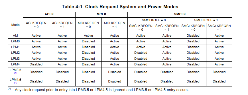
UCSCTL8 &=~ (SMCLKREQEN + MCLKREQEN);
when i use this code to initialize the clock mode,i found the current consumption is very large,when the micro-conntroller enter into LPM3 mode,the current is about 330uA,what is wrong in my code?can someboby help me point out the error in my code!
thank you!