This thread has been locked.

If you have a related question, please click the "Ask a related question" button in the top right corner. The newly created question will be automatically linked to this question.

High current when AVcc connected to DVcc via resistor

Other Parts Discussed in Thread: MSP430F2618

Hello!

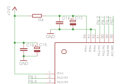
I had develop device on MSP430F2618. Connection of DVcc and AVcc: 


If R = 0, all is OK, but if R > 0, microcontroller supply current more then 300 mA, and it is heated. 

Where I am wrong?

  • This is a very common schematic for an MSP430 design, with R4 set to something like 10 or 20 ohms. It can really help to keep the board's digital noise away from the AVcc pin. So, there is nothing wrong with the schematic you show.

    Steve

  • Why the current of consumption of F2618 is more 300 mA if R4 not null?

    This problem is on two different chips and pcb boards. I try connect F2618 without any external components and the problem remains..

  • Indeed this is a very common setup and if your PCB follows the above schematics, all should be well.

    So if it isn't, my guess is: oscillation. Check your VCC with an oscilloscope.

    A common cause for oscillation is that the VCC-generating voltage regulator is missing a suffucient low-ESR capacitor (usually 100nF ceramic) directly on its output and input. If VCC oscillates, all is (more or less, rather less) well, as long as DVCC and AVCC oscillate with the same frequency and amplitude. But once you add R4, they are not in phase anymore and cross-currents flow from DVCC to AVCC and back, causing high currents and therefore high heating on the clamp diodes.

  • I am having a strange heating problem as well.

    Why would the current flow through the chip itself if DVCC and AVCC are different?  Aren't they supplying different components of the chip?

    In my circuit, I am supplying AVCC through a separate LDO.

    3 of my boards heat out of control, while 2 stay at roughly room temperature during operation.

    I have run with this LDO configuration previously using a F1611 without this happening, but this heating problem only shows up in my new design.

    It does look like the heating starts near the pin 1 corner right when I connect power and look at it through a heat camera.

    Should I not supply AVCC separately? Why would this happen on only 3 out of 5 of my boards?

  • I have solved this problem. This is latch-up effect, when AVcc not equally DVcc at power on.

    R-C chain adds a delay to set Vcc between AVcc and DVcc. 

    If your LDOs start-up in different time, you may see the some effect as me.

    I have changed resistor to Chip Bead to solve this problem.

  • Indeed, AVcc should be always equal to DVcc and must not be higher.
    The datasheet does not tell how big the tolerance is, but I guess that AVcc being more than 0.2V higher than DVcc will lead to dangerous cross-currents. And if this happens at core logic startup (brownout), latchups may happen inside the port logic.

    Usual setups generate AVcc from DVcc with an R/C filter and separate GND wiring (to the filter point). A separate LDO might have better voltage stability but also different startup times (LDOs are usually faster than any switching regulator)

**Attention** This is a public forum