This thread has been locked.

If you have a related question, please click the "Ask a related question" button in the top right corner. The newly created question will be automatically linked to this question.

MSP430 Power Consumption

Hi,


I want to measure the power consumption of an MSP430 device over the time. For that setup I use the MSP430F5529LP Launchpad.

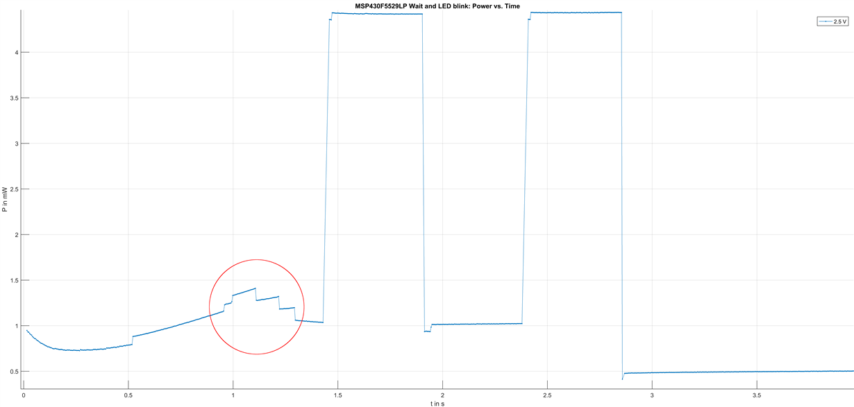
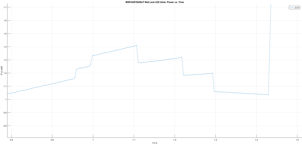
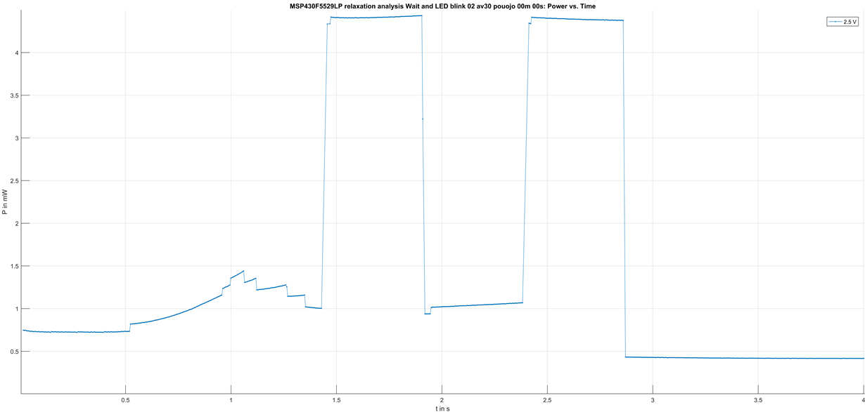
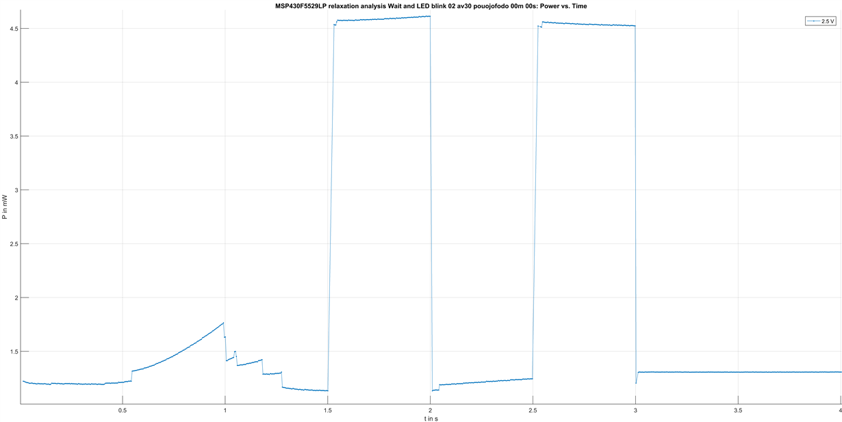
I did some measurements and I have observed interesting jumps in the power consumption:

The used test program is:

#include <msp430.h> 

void terminateAllGPIOs(){
	// All pins are outputs
	// All pins pulled to low
	P1DIR = 0xFF;
	P1OUT = 0x00;
	P2DIR = 0xFF;
	P2OUT = 0x00;
	P3DIR = 0xFF;
	P3OUT = 0x00;
	P4DIR = 0xFF;
	P4OUT = 0x00;
	P5DIR = 0xFF;
	P5OUT = 0x00;
	P6DIR = 0xFF;
	P6OUT = 0x00;
	P7DIR = 0xFF;
	P7OUT = 0x00;
	P8DIR = 0xFF;
	P8OUT = 0x00;
}

void initTests()
{
	// Configure LED on P1.0
	P1DIR = BIT0; // P1.0 output
}

void leftLEDBlink() {
	int i;
	__delay_cycles(1000000); // ~1 second delay
    for(i=0;i<4;i++)
    {
		__delay_cycles(500000); // ~0.5 second delay
		P1OUT^=(BIT0);    // toggle the led
    }
}

/*
 * main.c
 */
void main(void) {
    WDTCTL = WDTPW | WDTHOLD;	// Stop watchdog timer
	terminateAllGPIOs();

    // Disable USB powering
    USBPWRCTL &= ~VUSBEN; // Disable USB LDO (3.3 V)
    USBPWRCTL &= ~SLDOEN;// Disable secondary USB LDO (1.8 V)

	initTests();
	leftLEDBlink();
}

Do you have ideas what causes these jumps?

I did already experiment with

  • different frequencies on MCLK, SMCLK, ACLK
  • different core voltages (PMMCOREVx)
  • different programs
  • keeping the pins and usb in standard configuration
  • pull the supply voltage low / high impedance before the measurement

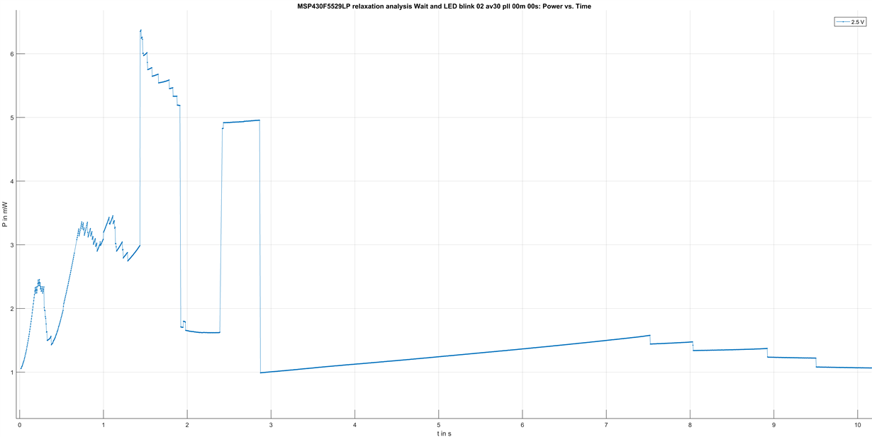
The consumption behaviour can be quite different. Here is an example without calling the function terminateAllGPIOs() and without disabling the USB powering but pulling the supply voltage to 0 V before the measurement instead of keeping it high impedant:

Do you have an explanation for the jumps in the power consumption?

Best regards

Martin

  • How exactly are you measuring the power?

    How are the connections to the other components of the LaunchPad board configured?
  • Martin,

    if you do not terminate or initialize the GPIO they are floating which can cause unpredicted current consumption.

    However when you measure with initialized IO's especially the ripples before the GPIO toggling starts is interesting.
    Also strange is that the device takes up to 1.5s until the first LED toggling is visible.

    By the way you code will somehow run into the nowhere because after your for loop in the LED blink loop you do not enter an LPM are placed a while(1).

    Best regards,
    Dietmar
  • I measure with an Agilent Measurement Mainframe E5270B with an E5287A "High Resolution Source/Monitor Unit".

    The Agilent device offers a 4 wire measurement method, nevertheless we are only able to achieve a 3-wire-measurement.

    The Agilent sources the power and measures the current. It measures U_sense and controls U_force, so that U_sense is at the desired voltage.
    The power steps introduced by this control are expected to be much smaller then these shown in the picture:

    To minimize the error introduced by the ground wire resistance we are calculating the consumed power with the calculated voltage U_DUT. The device under test (DUT) is the MSP430F5529LP:

    Connection to the Launchpad was mad as following:

    Combining sense and force and providing both via one pin does not show a different behaviour.

  • Dear D. Walther,

    > if you do not terminate or initialize the GPIO they are floating which can cause unpredicted current consumption.
    Yes, I have observed your described behaiour. The ripples are stronger and the overall consumption is higher when not terminating the GPIOs.

    >However when you measure with initialized IO's especially the ripples before the GPIO toggling starts is interesting.
    That is exactly what I am interested in.

    >Also strange is that the device takes up to 1.5s until the first LED toggling is visible.
    This delay is introduced due to the program.
    There is a mistake in my comments. The first delay waits for 1 second and directly after entering the loop there is another delay for about 0.5 seconds adding up to the initial delay of about 1.5 seconds.

    >By the way you code will somehow run into the nowhere because after your for loop in the LED blink loop you do not enter an LPM are placed a while(1).
    Yes this is intended. I research other programs ending in low power modes. I want to compare their consumption and sometimes use bad programming intentional to specify the advantages.

    Best regards
    Martin
  • Hi Martin,

    ok understood where the delay comes from.
    Can you please set the PortJ (JTAG port) pins to output low to prevent them beeing floating and check the behavior again?

    Best regards,
    Dietmar
  • With the default settings, the FLL is enabled and tries to synchronize the DCO to REFO. These jumps could be explained by the DCO going through different frequency steps.
    Try disabling the FLL ("_bis_SR_register(SCG0);") at the beginning.

  • Hi

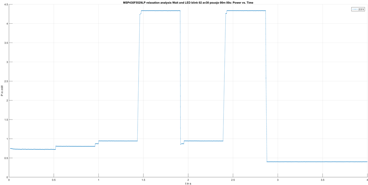
    I tested for the tips of Clemens Ladisch and Dietmar Walther. This are the results:

    1. When initializing the GPIOs, the JTAG port and disabling USB:

    2. When initializing the GPIOs, the JTAG port, disabling USB and disabling DCO and FLL:

    The program for the first image does not include the clock reconfiguration "initClocks()" and the setting of SCG0 and SCG1.

    The used program for the second image:

    #include <msp430.h>
    #include "driverlib.h" // "MSPware" must be installed via CCS -> View -> CCS App Center
    
    void terminateAllGPIOs(){
    	// All pins are outputs
    	// All pins pulled to low
    	P1DIR = 0xFF;
    	P1OUT = 0x00;
    	P2DIR = 0xFF;
    	P2OUT = 0x00;
    	P3DIR = 0xFF;
    	P3OUT = 0x00;
    	P4DIR = 0xFF;
    	P4OUT = 0x00;
    	P5DIR = 0xFF;
    	P5OUT = 0x00;
    	P6DIR = 0xFF;
    	P6OUT = 0x00;
    	P7DIR = 0xFF;
    	P7OUT = 0x00;
    	P8DIR = 0xFF;
    	P8OUT = 0x00;
    
    	// or
    	// Select pins secondary function
    	//P1SEL = 0xBE;
    
    	// or
    	// this if the register exists in the header file
    	//P1SEL2 = 0xEF
    }
    
    void terminateJTAG(){
    	// All pins are outputs
    	// All pins pulled to low
    	PJDIR = 0xFF;
    	PJOUT = 0x00;
    }
    
    void initClocks(){
        GPIO_setAsPeripheralModuleFunctionInputPin(
    		GPIO_PORT_P5,
    		GPIO_PIN2
        );
    
        GPIO_setAsPeripheralModuleFunctionOutputPin(
    		GPIO_PORT_P5,
    		GPIO_PIN3
        );
    
    	UCS_setExternalClockSource(
    		32768,		// Frequency of XT1 in Hz
    		4000000		// Frequency of XT2 in Hz
    	);
    
    	UCS_turnOnXT2(
    		UCS_XT2_DRIVE_4MHZ_8MHZ
    	);
    
    	UCS_initClockSignal(
    		UCS_MCLK,
    		UCS_XT2CLK_SELECT,
    		UCS_CLOCK_DIVIDER_4
    	);
    
    	UCS_initClockSignal(
    		UCS_SMCLK,
    		UCS_XT2CLK_SELECT,
    		UCS_CLOCK_DIVIDER_4
    	);
    
    	UCS_initClockSignal(
    		UCS_ACLK,
    		UCS_REFOCLK_SELECT,
    		UCS_CLOCK_DIVIDER_1
    	);
    }
    
    void initTests()
    {
    	// Configure LED on P1.0
    	P1DIR = BIT0; // P1.0 output
    }
    
    void leftLEDBlink() {
    	int i;
    	__delay_cycles(1000000); // 1.0 second delay; 0.1 second delay is 100000 cycles
        for(i=0;i<4;i++)
        {
    		__delay_cycles(500000); // 0.5 second delay; 0.1 second delay is 100000 cycles
    		P1OUT^=(BIT0);    // toggle the led
        }
    }
    
    //uint32_t mclk = 0;
    //uint32_t smclk = 0;
    //uint32_t aclk = 0;
    
    /*
     * main.c
     */
    void main(void) {
        WDTCTL = WDTPW | WDTHOLD;	// Stop watchdog timer
    
        // Initialize ports
    	terminateAllGPIOs();
    	terminateJTAG();
    
        // Initialize clocks
        initClocks();
        //aclk=UCS_getACLK();
        //mclk=UCS_getMCLK();
        //smclk=UCS_getSMCLK();
    
        // Disable USB powering
        USBPWRCTL &= ~VUSBEN; // Disable USB LDO (3.3 V)
        USBPWRCTL &= ~SLDOEN;// Disable secondary USB LDO (1.8 V)
    
        // Disable DCO
        _bis_SR_register(SCG1);
        // Disable FLL
        _bis_SR_register(SCG0);
    
    	initTests();
    	leftLEDBlink();
    }

    Neither initializing the JTAG ports nor switching of the DCO and FLL eliminates the "jumps" in the energy consumption.

    I thought that maybe some kind of internal power regulator causes the jumps. Do you have any idea about what I have missed?

  • The UCS_turnOnXT2() function waits until the crystal has started up. Try moving it to the end of the initialization. (But these strange steps certainly happen later.)

    And the fault flag for XT1 might still be set; try calling UCS_clearFaultFlag(UCS_XT1LFOFFG).

  • Yes, but it is needed in the next command where XT2 is assigned as "Main Clock Source (MCLK)". Do you propose to move the whole function "initClocks();" down? Stopping the DCO and FLL before may give problems as the DCO, as far as I researched, is the default clock source for MCLK.

    The time I expect for the settling is much lower than the observed "jumps" after 1 second. Thatswhy I did not care too much about the settling time.

    Could you propose me a program example and what behaviour you expect, please?

  • I'm not that familiar with the Agilent Measurement Mainframe E5270B so therefore it's maybe not a good question but I would like to ask it anyway.
    The voltage iduring this energy record is stable right?

    The LDO which is providing the Vcore voltage should not cause the issue becaue it regulates to the right value already during start-up and this will not take a 1s.

    I'm not sure how the rest of the Launch Pad influences this e.g. the emulation logic. You do not have the chance to measure it in standalone EVM right?

    Best regards,
    Dietmar

  • You could stop the FLL immediately, and the DCO later. But anyway:

    P1DIR = BIT0; // P1.0 output

    This line makes the pins P1.1…P1.7 inputs, so they float again.

  • > I'm not that familiar with the Agilent Measurement Mainframe E5270B so therefore it's maybe not a good question but I would like to ask >it anyway.
    > The voltage iduring this energy record is stable right?
    The Agilent holds the voltage U_sense measured between the sense wire directly attached to VCC on the board and the end of the ground wire constant. Depending on the current which is flowing there is a voltage drop caused by the GND wire. The drop voltage for the measurements we are facing is maximum 2.5 mV@2.5mA, R_GND=1 Ohm. (Please refer to my recent post <Aug 8, 2016 1:46 PM>)

    > The LDO which is providing the Vcore voltage should not cause the issue becaue it regulates to the right value already during start-up >and this will not take a 1s.
    I expect the same.

    > I'm not sure how the rest of the Launch Pad influences this e.g. the emulation logic. You do not have the chance to measure it in >standalone EVM right?
    The MSP430F5529LP has hardware jumpers to disconnect the debugger/programmer/external voltage regulator. During the measurement the jumpers are disconnected and a back-powering into the emulator should not be possible. (Please refer to the image of the microcontroller connection in my recent post <Aug 8, 2016 1:46 PM>)
  • Clemens Ladisch wrote:

    >P1DIR = BIT0; // P1.0 output

    >This line makes the pins P1.1…P1.7 inputs, so they float again.

    You are absolutely right. I changed the code to:

    P1DIR |= 1 << BIT0; // P1.0 output

    The new result when initializing the GPIOs, the JTAG port and disabling USB looks like that:

    The edges are now much sharper. There are still little jumps in the consumption.

  • BIT0 already is a bit maks; "1 << BIT0" results in the value 2, which corresponds to BIT1. (But all eight bits are already set.)

    Is this the version with the FLL enabled? Is your question answered?
  • P1DIR |= BIT0;

    Should do the job now. The code I used to generate the last image is already full functional as all are already outputs (from GPIO initialization) and the command is not needed. I only used it for an understandable source code.

    Important was, that I forgot the "or".  Thatswhy i cleared all the other bits by mistake.

    I thank you a lot for your help and have only these questions left:

    The edges are now much sharper. There are still little jumps in the consumption. Interesting is, that it looks like the energy consumption "jumps" to another level.

    1.

    If we look at the energy consumption around 1 second we see several steps. before 1 second there is just a delay function.around 1 second the microcontroller is entering the loop and afterwards again just a delay function. I would expect a change in the consumption while entering the loop. But I expect the same consumption in the delay parts before and after. Why is the consumption different?

    2.

    The fix of the floating inputs on port 1 suppressed a few "down-jumps" after 1s. Why does a floating input cause such "jumps"?

  • __delay_cycles() is implemented as one or multiple inline loops. It's possible that different loops are aligned differently and therefore result in different flash access patterns. Try creating a separate function wait_one_second() and ensure that it is not inlined, then all waits should behave the same.

    The shoot-through current increases when the input's voltage moves so that both FETs are partially switched on. Apparently, something causes some gate to discharge quickly.
  • Hi Martin,

    regading #1:
    As Clemens arelady wrote it might depends on the memory address and the flash alignment of these functions. If you execute the loop exaclty from the same location it should be exaclty the same.

    regarding #2:
    If you have configured a GPIO as input and do not terminate it via pull-up or pull-down. The signal might float to a value where it would normally switch and this then would consume current: There is a good application report covering this aspect of Schmitt Trigger inputs

    www.ti.com/.../scea046.pdf please see figure 1, while keeping in mind, the values differ from the MSP430, as this is dependent on process and other design parameters. But the principle characteristic applies.

    Best regards,
    Dietmar
  • >__delay_cycles() is implemented as one or multiple inline loops. It's possible that different loops are aligned differently and therefore result in different flash >access patterns. Try creating a separate function wait_one_second() and ensure that it is not inlined, then all waits should behave the same.

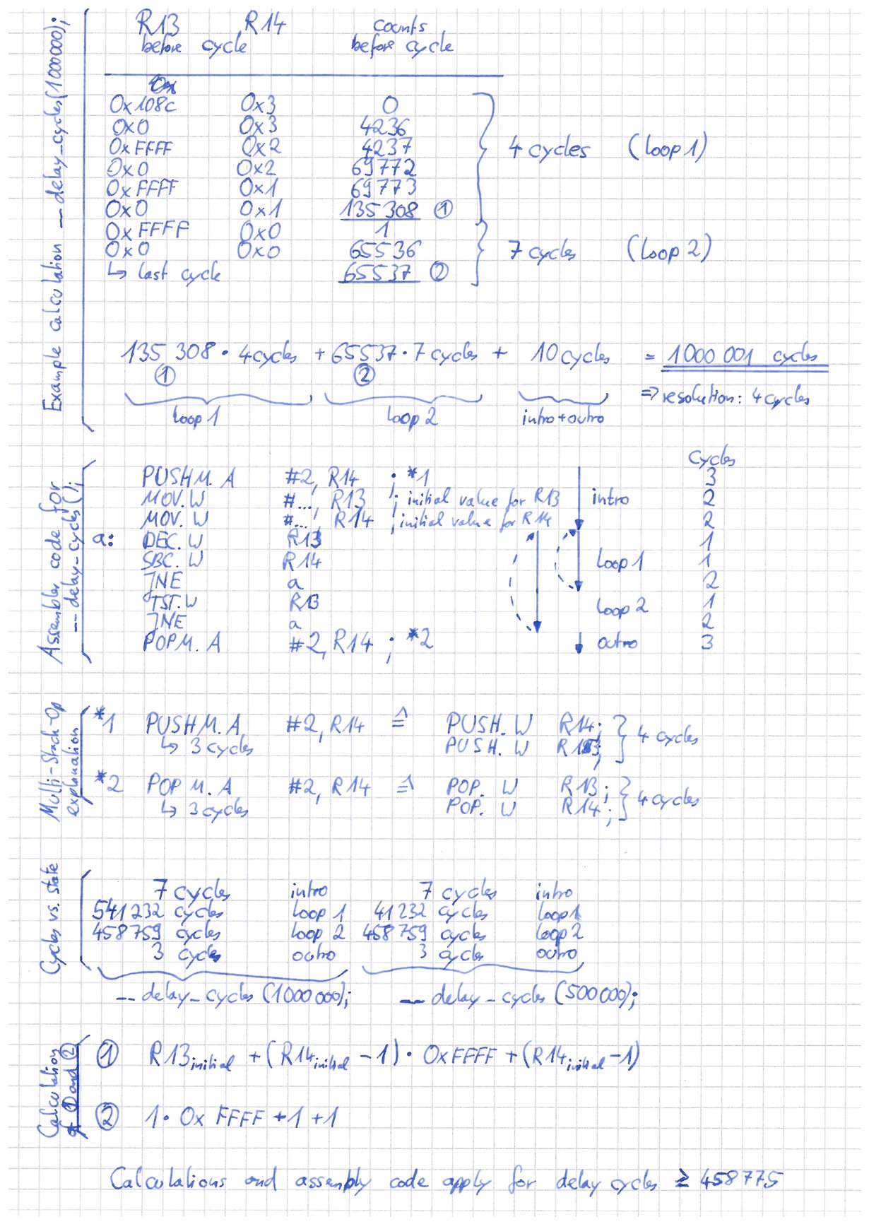
    I have analyzed the __delay_cycles(); function in assembler. It is not accessing the memory/flash at all. It operates completely on CPU registers R13 and R14.

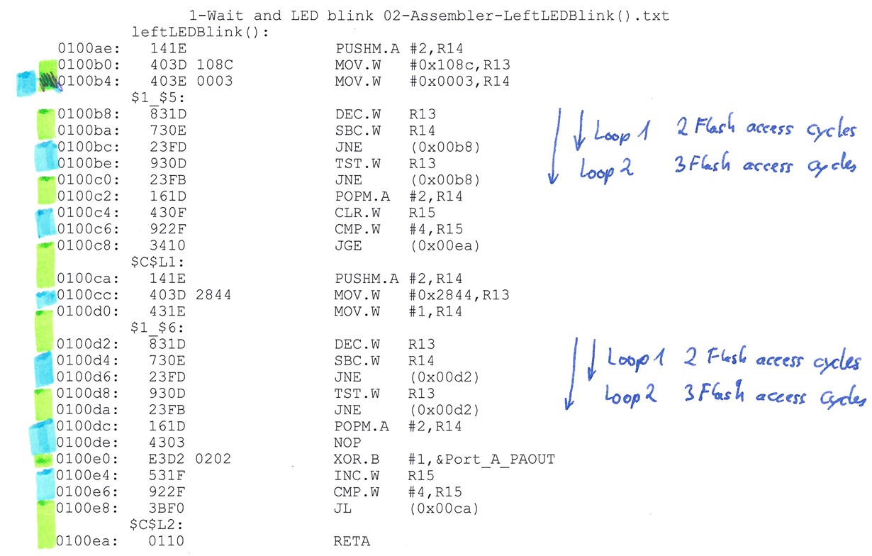
    I concluded my analysis in one sheet:

    For the best understanding start with the section "Assembler code for __delay_cycles();"

    > Apparently, something causes some gate to discharge quickly.


    This is exactly what is not clear to me. Do you have any ideas?

  • What would help more is the disassembly window where we can see the address alignment of the loops. Where the disassebmly code is placed in the memory? It's not a question of cylces most probablys this is the same but the location in the memory is interesting.

    Best regards,
    Dietmar
  • I have analyzed the __delay_cycles(); function

    There is no single __delay_cycles() function; the compiler generates inline code adjusted for the cycle count. This is why we're asking you to put a single invocation of __delay_cycles() into a separate function.

    It is not accessing the memory/flash at all.

    The CPU instructions are fetched from flash. Prefetching and 32-bit alignment (if they exist) are not documented at all.

  • There is no single __delay_cycles() function; the compiler generates inline code adjusted for the cycle count. This is why we're asking you to put a single invocation of __delay_cycles() into a separate function.

    Yes, you are right. The generation of code is different for different numbers of cycles. I checked, that the code generated is similar in the range:

    1000001 <= delay_cycles <= 458775

    I guess that even for a cycle count above 1000001 the assembler structure stays the same. I have seen, that the assembler structure changes below 458775 cycles.

    The complete assembler code for the observed program:

    [...]
    00fff2:   441A 441A           MOV.W   0x441a(R4),R10
    00fff6:   441A 441A           MOV.W   0x441a(R4),R10
    00fffa:   441A 441A           MOV.W   0x441a(R4),R10
    00fffe:   4400                BR      R4
            _auto_init_hold_wdt():
    010000:   142A                PUSHM.A #3,R10
    010002:   1840 421A 015C      MOVX.W  &Watchdog_Timer_WDTCTL,R10
    010008:   1840 40B2 5A80 015C MOVX.W  #0x05a80,&Watchdog_Timer_WDTCTL
    010010:   008F 0000           MOVA    #0x00000,R15
    010014:   009F 0000           CMPA    #0x00000,R15
    010018:   2413                JEQ     (0x0040)
    01001a:   0089 0000           MOVA    #0x00000,R9
    01001e:   0088 0000           MOVA    #0x00000,R8
    010022:   3C0C                JMP     (0x003c)
            $C$L1:
    010024:   090C                MOVA    @R9,R12
    010026:   4C7F                MOV.B   @R12+,R15
    010028:   065F                RLAM.W  #2,R15
    01002a:   1800 4F5F 0000      MOVX.A  0x00000(R15),R15
    010030:   00A9 0004           ADDA    #0x00004,R9
    010034:   090D                MOVA    @R9,R13
    010036:   134F                CALLA   R15
    010038:   00A9 0004           ADDA    #0x00004,R9
            $C$L2:
    01003c:   08D9                CMPA    R8,R9
    01003e:   23F2                JNE     (0x0024)
            $C$L3:
    010040:   C27A                BIC.B   #8,R10
    010042:   D03A 5A08           BIS.W   #0x5a08,R10
    010046:   1840 4A82 015C      MOVX.W  R10,&Watchdog_Timer_WDTCTL
    01004c:   008F 0000           MOVA    #0x00000,R15
    010050:   009F 0000           CMPA    #0x00000,R15
    010054:   2409                JEQ     (0x0068)
    010056:   008A 0000           MOVA    #0x00000,R10
    01005a:   3C03                JMP     (0x0062)
            $C$L4:
    01005c:   136A                CALLA   @R10
    01005e:   00AA 0004           ADDA    #0x00004,R10
            $C$L5:
    010062:   009A 0000           CMPA    #0x00000,R10
    010066:   23FA                JNE     (0x005c)
            $C$L6:
    010068:   1628                POPM.A  #3,R10
    01006a:   0110                RETA    
            terminateAllGPIOs():
    01006c:   43F2 0204           MOV.B   #-1,&Port_A_PADIR
    010070:   43C2 0202           CLR.B   &Port_A_PAOUT
    010074:   43F2 0205           MOV.B   #-1,&Port_1_2_P2DIR
    010078:   43C2 0203           CLR.B   &Port_1_2_P2OUT
    01007c:   43F2 0224           MOV.B   #-1,&Port_B_PBDIR
    010080:   43C2 0222           CLR.B   &Port_B_PBOUT
    010084:   43F2 0225           MOV.B   #-1,&Port_3_4_P4DIR
    010088:   43C2 0223           CLR.B   &Port_3_4_P4OUT
    01008c:   43F2 0244           MOV.B   #-1,&Port_C_PCDIR
    010090:   43C2 0242           CLR.B   &Port_C_PCOUT
    010094:   43F2 0245           MOV.B   #-1,&Port_5_6_P6DIR
    010098:   43C2 0243           CLR.B   &Port_5_6_P6OUT
    01009c:   43F2 0264           MOV.B   #-1,&Port_D_PDDIR
    0100a0:   43C2 0262           CLR.B   &Port_D_PDOUT
    0100a4:   43F2 0265           MOV.B   #-1,&Port_7_8_P8DIR
    0100a8:   43C2 0263           CLR.B   &Port_7_8_P8OUT
    0100ac:   0110                RETA    
            leftLEDBlink():
    0100ae:   141E                PUSHM.A #2,R14
    0100b0:   403D 108C           MOV.W   #0x108c,R13
    0100b4:   403E 0003           MOV.W   #0x0003,R14
            $1_$5:
    0100b8:   831D                DEC.W   R13
    0100ba:   730E                SBC.W   R14
    0100bc:   23FD                JNE     (0x00b8)
    0100be:   930D                TST.W   R13
    0100c0:   23FB                JNE     (0x00b8)
    0100c2:   161D                POPM.A  #2,R14
    0100c4:   430F                CLR.W   R15
    0100c6:   922F                CMP.W   #4,R15
    0100c8:   3410                JGE     (0x00ea)
            $C$L1:
    0100ca:   141E                PUSHM.A #2,R14
    0100cc:   403D 2844           MOV.W   #0x2844,R13
    0100d0:   431E                MOV.W   #1,R14
            $1_$6:
    0100d2:   831D                DEC.W   R13
    0100d4:   730E                SBC.W   R14
    0100d6:   23FD                JNE     (0x00d2)
    0100d8:   930D                TST.W   R13
    0100da:   23FB                JNE     (0x00d2)
    0100dc:   161D                POPM.A  #2,R14
    0100de:   4303                NOP     
    0100e0:   E3D2 0202           XOR.B   #1,&Port_A_PAOUT
    0100e4:   531F                INC.W   R15
    0100e6:   922F                CMP.W   #4,R15
    0100e8:   3BF0                JL      (0x00ca)
            $C$L2:
    0100ea:   0110                RETA    
            main():
    0100ec:   40B2 5A80 015C      MOV.W   #0x5a80,&Watchdog_Timer_WDTCTL
    0100f2:   13B1 006C           CALLA   #terminateAllGPIOs
    0100f6:   13B1 0110           CALLA   #terminateJTAG
    0100fa:   F0B2 F7FF 0908      AND.W   #0xf7ff,&USB_Control_USBPWRCTL
    010100:   F0B2 EFFF 0908      AND.W   #0xefff,&USB_Control_USBPWRCTL
    010106:   13B1 011C           CALLA   #initTests
    01010a:   13B1 00AE           CALLA   #leftLEDBlink
    01010e:   0110                RETA    
            terminateJTAG():
    010110:   40B2 00FF 0324      MOV.W   #0x00ff,&Port_J_PJDIR
    010116:   4382 0322           CLR.W   &Port_J_PJOUT
    01011a:   0110                RETA    
            initTests():
    01011c:   D3D2 0204           BIS.B   #1,&Port_A_PADIR
    010120:   0110                RETA    
            _system_pre_init():
    010122:   431C                MOV.W   #1,R12
    010124:   0110                RETA    
            C$$EXIT(), abort():
    010126:   4303                NOP     
            $C$L1:
    010128:   3FFF                JMP     (PMM__Power_Management_System_SVSMIO)
    01012a:   FFFF FFFF           AND.B   @R15+,0xffff(R15)
    01012e:   FFFF FFFF           AND.B   @R15+,0xffff(R15)
    010132:   FFFF FFFF           AND.B   @R15+,0xffff(R15)
    [...]

    The code resides in the flash region from 0x10000 to 0x010128.


    The first __delay_cyles(1000000); resides in the flash region: 0x100ae .. 0x100c2

    The second __delay_cycles(500000); resides in the flash region: 0x100ca .. 0x100dc

    Is this difference really mattering?

    As far as I understand that means all code is placed in the "flash2" region. Here the excerpt from the appropriate linker file:

    [...]
    /****************************************************************************/
    /* Specify the system memory map                                            */
    /****************************************************************************/
    
    MEMORY
    {
        SFR                     : origin = 0x0000, length = 0x0010
        PERIPHERALS_8BIT        : origin = 0x0010, length = 0x00F0
        PERIPHERALS_16BIT       : origin = 0x0100, length = 0x0100
        RAM                     : origin = 0x2400, length = 0x2000
        USBRAM                  : origin = 0x1C00, length = 0x0800
        INFOA                   : origin = 0x1980, length = 0x0080
        INFOB                   : origin = 0x1900, length = 0x0080
        INFOC                   : origin = 0x1880, length = 0x0080
        INFOD                   : origin = 0x1800, length = 0x0080
        FLASH                   : origin = 0x4400, length = 0xBB80
        FLASH2                  : origin = 0x10000,length = 0x14400
        INT00                   : origin = 0xFF80, length = 0x0002
        INT01                   : origin = 0xFF82, length = 0x0002
    [...]
    }
    
    /****************************************************************************/
    /* Specify the sections allocation into memory                              */
    /****************************************************************************/
    
    SECTIONS
    {
        .bss        : {} > RAM                  /* Global & static vars              */
        .data       : {} > RAM                  /* Global & static vars              */
        .TI.noinit  : {} > RAM                  /* For #pragma noinit                */
        .sysmem     : {} > RAM                  /* Dynamic memory allocation area    */
        .stack      : {} > RAM (HIGH)           /* Software system stack             */
    
    #ifndef __LARGE_DATA_MODEL__
        .text       : {}>> FLASH                /* Code                              */
    #else
        .text       : {}>> FLASH2 | FLASH       /* Code                              */
    #endif
        .text:_isr  : {} > FLASH                /* ISR Code space                    */
        .cinit      : {} > FLASH                /* Initialization tables             */
    #ifndef __LARGE_DATA_MODEL__
        .const      : {} > FLASH                /* Constant data                     */
    #else
        .const      : {} > FLASH | FLASH2       /* Constant data                     */
    #endif
        .cio        : {} > RAM                  /* C I/O Buffer                      */
    
        .pinit      : {} > FLASH                /* C++ Constructor tables            */
        .init_array : {} > FLASH                /* C++ Constructor tables            */
        .mspabi.exidx : {} > FLASH              /* C++ Constructor tables            */
        .mspabi.extab : {} > FLASH              /* C++ Constructor tables            */
    
        .infoA     : {} > INFOA              /* MSP430 INFO FLASH Memory segments */
        .infoB     : {} > INFOB
        .infoC     : {} > INFOC
        .infoD     : {} > INFOD
    
        /* MSP430 Interrupt vectors          */
        .int00       : {}               > INT00
        .int01       : {}               > INT01
        .int02       : {}               > INT02
    [...]
    }
    
    /****************************************************************************/
    /* Include peripherals memory map                                           */
    /****************************************************************************/
    
    -l msp430f5529.cmd


    All cut outs are marked with "[...]".

  • Hi Martin,

    I think I have an explanation but I was called for another urgent topic and therefore the final response is a bit delayed. Please apologize for this. I will come back to this thread latest by mid of next week.

    Best regards,
    Dietmar
  • Hi Martin,

    sorry for delay I had to work on some other things and also had to clarify how to communicate this behavior (in case my assumption is right). As mentioned in this post the flash alignment on our F5xx/F6xx is not explained in detail in the user's guide but I can tell you here that we have 32 bit flash interface on this 16 bit CPU architecture. Means we have a buffer in between to catch the 32 bits.

    In your case both loops are located within 5 words thats why alignment is not the problem you always need 3 flash access cycles. But the structure of the for loops explains it. And you did a great pre-work (hand written post) here analysing which loops were executed how often.

    Please see my picture below (red and blue marked locations represents a single flash access (32 bits)):

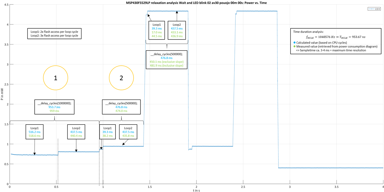
    For the 1s loop you have nearly the same number  2xflash access loops in relation to the 3xflash access loops which brings to overall power consumption a bit down.

    On the 0.5s loop you have a relation of ~1:11 (2xflash access loop vs. 3xflash_access loop) which brings overall consumption up.

    An easy test would be to make the 0.5s loop also 1s long and check in the disassembly if the excaclty the same loop executions will take place. Then repeat the current measurements. If you still see the difference it's something else.

    Best regards,
    Dietmar

  • Hi Dietmar

    I was also busy in the last days. I did some further investigations on the flash and also found out, that the slightly different memory region unlikely causes the different energy consumtion. Your explanation with the flash cycles explains the difference in the energy consumption within one loop.

    The alignment of assembler code is slightly different in my version (maybe related to different compiler versions of us). Nevertheless the first loop needs 2 flash accesses and the second 3 flash accesses:

    If you compare (1) and (2) in the next image you see a static power consumption deviation between the two implementations of the same loop. I have no explanation for that yet. Do you have an idea for the cause of that?

  • Hi

    I wanted to study the offset I asked for in the last post: For that matter I added another __delay_cycles(1000000); at the end of the program. This leads to another sorting of functions in the memory/assembler. Furthermore it leads to another power consumption profile. Both measurements are reproducable. I flashed in the order:

    program 1 -> program 2 -> program 1 -> program 2

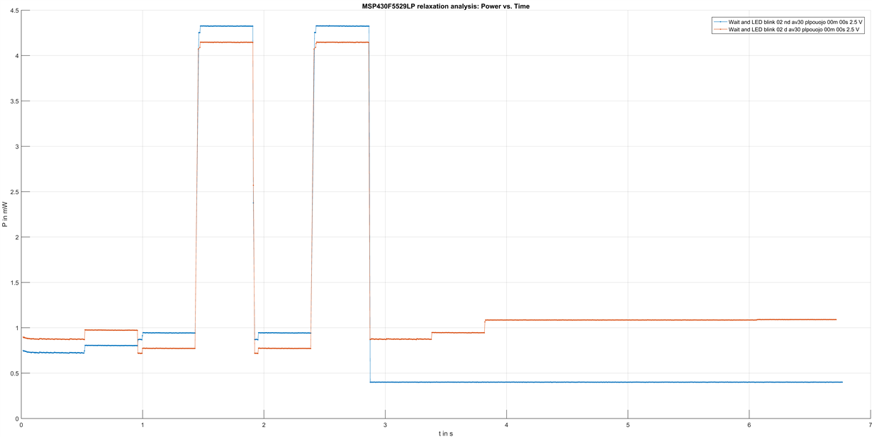
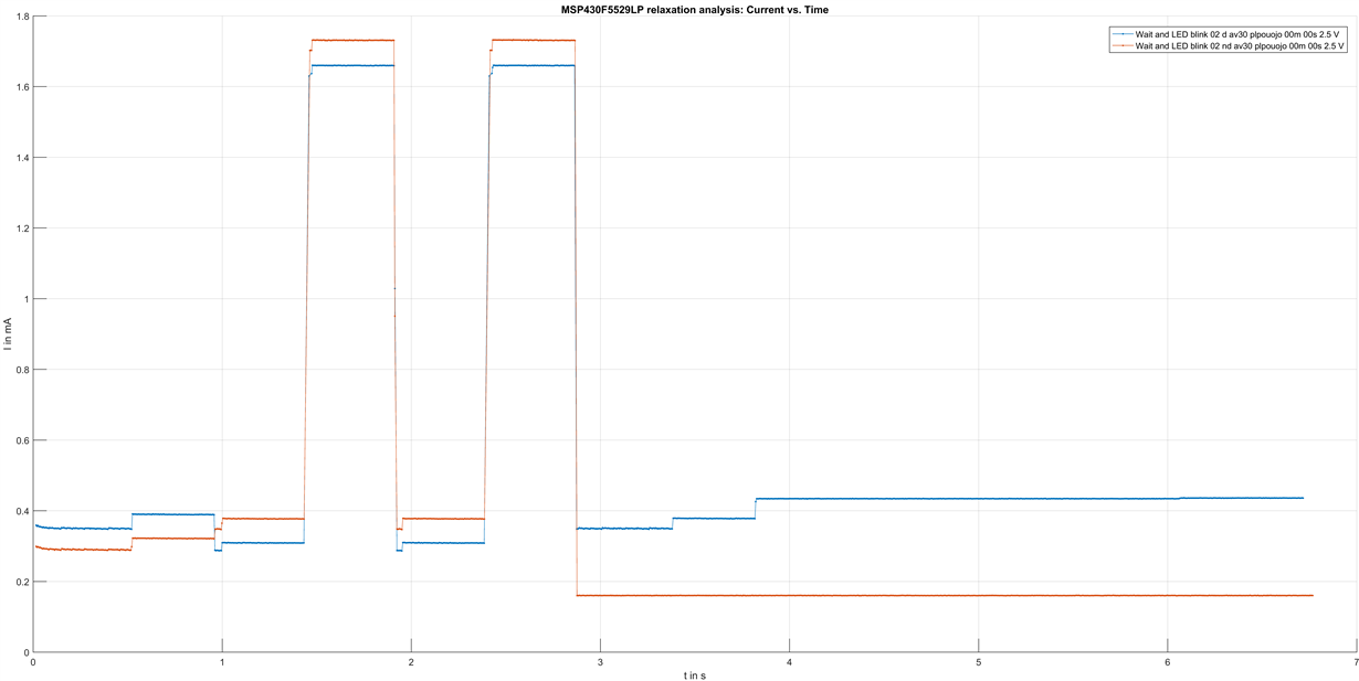
    Furthermore I did multiple measurements to check for variations. The variations are minimal and the results reproducable so that I expect this as a behaviour from the microcontroller. The following image shows the comparison of both programs:

    The blue graph is the original program. This will be referenced as program 1 in this post.

    The orange graph is the original program with an additional __delay_cycles(1000000); at the end. This will be referenced as program 2 in this post.

    The source codes for program 1:

    #include <msp430.h>
    
    void terminateAllGPIOs(){
    	// All pins are outputs
    	// All pins pulled to low
    	P1DIR = 0xFF;
    	P1OUT = 0x00;
    	P2DIR = 0xFF;
    	P2OUT = 0x00;
    	P3DIR = 0xFF;
    	P3OUT = 0x00;
    	P4DIR = 0xFF;
    	P4OUT = 0x00;
    	P5DIR = 0xFF;
    	P5OUT = 0x00;
    	P6DIR = 0xFF;
    	P6OUT = 0x00;
    	P7DIR = 0xFF;
    	P7OUT = 0x00;
    	P8DIR = 0xFF;
    	P8OUT = 0x00;
    
    	// or
    	// Select pins secondary function
    	//P1SEL = 0xBE;
    
    	// or
    	// this if the register exists in the header file
    	//P1SEL2 = 0xEF
    }
    
    void terminateJTAG(){
    	// All pins are outputs
    	// All pins pulled to low
    	PJDIR = 0xFF;
    	PJOUT = 0x00;
    }
    
    void initTests()
    {
    	// Configure LED on P1.0
    	P1DIR |= BIT0; // P1.0 output
    }
    
    void leftLEDBlink() {
    	int i;
    	__delay_cycles(1000000); // 1.0 second delay; 0.1 second delay is 100000 cycles
    
        for(i=0;i<4;i++)
        {
    		__delay_cycles(500000); // 0.5 second delay; 0.1 second delay is 100000 cycles
    		P1OUT^=(BIT0);    // toggle the led
        }
        //__delay_cycles(1000000);
    }
    
    /*
     * main.c
     */
    void main(void) {
        WDTCTL = WDTPW | WDTHOLD;	// Stop watchdog timer
    	terminateAllGPIOs();
    	terminateJTAG();
    
        // Disable USB powering
        USBPWRCTL &= ~VUSBEN; // Disable USB LDO (3.3 V)
        USBPWRCTL &= ~SLDOEN;// Disable secondary USB LDO (1.8 V)
    
    	initTests();
    	leftLEDBlink();
    
    }
    

    The source code for program 2:

    #include <msp430.h>
    
    void terminateAllGPIOs(){
    	// All pins are outputs
    	// All pins pulled to low
    	P1DIR = 0xFF;
    	P1OUT = 0x00;
    	P2DIR = 0xFF;
    	P2OUT = 0x00;
    	P3DIR = 0xFF;
    	P3OUT = 0x00;
    	P4DIR = 0xFF;
    	P4OUT = 0x00;
    	P5DIR = 0xFF;
    	P5OUT = 0x00;
    	P6DIR = 0xFF;
    	P6OUT = 0x00;
    	P7DIR = 0xFF;
    	P7OUT = 0x00;
    	P8DIR = 0xFF;
    	P8OUT = 0x00;
    
    	// or
    	// Select pins secondary function
    	//P1SEL = 0xBE;
    
    	// or
    	// this if the register exists in the header file
    	//P1SEL2 = 0xEF
    }
    
    void terminateJTAG(){
    	// All pins are outputs
    	// All pins pulled to low
    	PJDIR = 0xFF;
    	PJOUT = 0x00;
    }
    
    void initTests()
    {
    	// Configure LED on P1.0
    	P1DIR |= BIT0; // P1.0 output
    }
    
    void leftLEDBlink() {
    	int i;
    	__delay_cycles(1000000); // 1.0 second delay; 0.1 second delay is 100000 cycles
    
        for(i=0;i<4;i++)
        {
    		__delay_cycles(500000); // 0.5 second delay; 0.1 second delay is 100000 cycles
    		P1OUT^=(BIT0);    // toggle the led
        }
        __delay_cycles(1000000);
    }
    
    /*
     * main.c
     */
    void main(void) {
        WDTCTL = WDTPW | WDTHOLD;	// Stop watchdog timer
    	terminateAllGPIOs();
    	terminateJTAG();
    
        // Disable USB powering
        USBPWRCTL &= ~VUSBEN; // Disable USB LDO (3.3 V)
        USBPWRCTL &= ~SLDOEN;// Disable secondary USB LDO (1.8 V)
    
    	initTests();
    	leftLEDBlink();
    
    }
    

    The assembler memory dump for program 1:

    00fffe:   4400                BR      R4
            _auto_init_hold_wdt():
    010000:   142A                PUSHM.A #3,R10
    010002:   1840 421A 015C      MOVX.W  &Watchdog_Timer_WDTCTL,R10
    010008:   1840 40B2 5A80 015C MOVX.W  #0x05a80,&Watchdog_Timer_WDTCTL
    010010:   008F 0000           MOVA    #0x00000,R15
    010014:   009F 0000           CMPA    #0x00000,R15
    010018:   2413                JEQ     (0x0040)
    01001a:   0089 0000           MOVA    #0x00000,R9
    01001e:   0088 0000           MOVA    #0x00000,R8
    010022:   3C0C                JMP     (0x003c)
            $C$L1:
    010024:   090C                MOVA    @R9,R12
    010026:   4C7F                MOV.B   @R12+,R15
    010028:   065F                RLAM.W  #2,R15
    01002a:   1800 4F5F 0000      MOVX.A  0x00000(R15),R15
    010030:   00A9 0004           ADDA    #0x00004,R9
    010034:   090D                MOVA    @R9,R13
    010036:   134F                CALLA   R15
    010038:   00A9 0004           ADDA    #0x00004,R9
            $C$L2:
    01003c:   08D9                CMPA    R8,R9
    01003e:   23F2                JNE     (0x0024)
            $C$L3:
    010040:   C27A                BIC.B   #8,R10
    010042:   D03A 5A08           BIS.W   #0x5a08,R10
    010046:   1840 4A82 015C      MOVX.W  R10,&Watchdog_Timer_WDTCTL
    01004c:   008F 0000           MOVA    #0x00000,R15
    010050:   009F 0000           CMPA    #0x00000,R15
    010054:   2409                JEQ     (0x0068)
    010056:   008A 0000           MOVA    #0x00000,R10
    01005a:   3C03                JMP     (0x0062)
            $C$L4:
    01005c:   136A                CALLA   @R10
    01005e:   00AA 0004           ADDA    #0x00004,R10
            $C$L5:
    010062:   009A 0000           CMPA    #0x00000,R10
    010066:   23FA                JNE     (0x005c)
            $C$L6:
    010068:   1628                POPM.A  #3,R10
    01006a:   0110                RETA   
            terminateAllGPIOs():
    01006c:   43F2 0204           MOV.B   #-1,&Port_A_PADIR
    010070:   43C2 0202           CLR.B   &Port_A_PAOUT
    010074:   43F2 0205           MOV.B   #-1,&Port_1_2_P2DIR
    010078:   43C2 0203           CLR.B   &Port_1_2_P2OUT
    01007c:   43F2 0224           MOV.B   #-1,&Port_B_PBDIR
    010080:   43C2 0222           CLR.B   &Port_B_PBOUT
    010084:   43F2 0225           MOV.B   #-1,&Port_3_4_P4DIR
    010088:   43C2 0223           CLR.B   &Port_3_4_P4OUT
    01008c:   43F2 0244           MOV.B   #-1,&Port_C_PCDIR
    010090:   43C2 0242           CLR.B   &Port_C_PCOUT
    010094:   43F2 0245           MOV.B   #-1,&Port_5_6_P6DIR
    010098:   43C2 0243           CLR.B   &Port_5_6_P6OUT
    01009c:   43F2 0264           MOV.B   #-1,&Port_D_PDDIR
    0100a0:   43C2 0262           CLR.B   &Port_D_PDOUT
    0100a4:   43F2 0265           MOV.B   #-1,&Port_7_8_P8DIR
    0100a8:   43C2 0263           CLR.B   &Port_7_8_P8OUT
    0100ac:   0110                RETA   
            leftLEDBlink():
    0100ae:   141E                PUSHM.A #2,R14
    0100b0:   403D 108C           MOV.W   #0x108c,R13
    0100b4:   403E 0003           MOV.W   #0x0003,R14
            $1_$5:
    0100b8:   831D                DEC.W   R13
    0100ba:   730E                SBC.W   R14
    0100bc:   23FD                JNE     (0x00b8)
    0100be:   930D                TST.W   R13
    0100c0:   23FB                JNE     (0x00b8)
    0100c2:   161D                POPM.A  #2,R14
    0100c4:   430F                CLR.W   R15
    0100c6:   922F                CMP.W   #4,R15
    0100c8:   3410                JGE     (0x00ea)
            $C$L1:
    0100ca:   141E                PUSHM.A #2,R14
    0100cc:   403D 2844           MOV.W   #0x2844,R13
    0100d0:   431E                MOV.W   #1,R14
            $1_$6:
    0100d2:   831D                DEC.W   R13
    0100d4:   730E                SBC.W   R14
    0100d6:   23FD                JNE     (0x00d2)
    0100d8:   930D                TST.W   R13
    0100da:   23FB                JNE     (0x00d2)
    0100dc:   161D                POPM.A  #2,R14
    0100de:   4303                NOP    
    0100e0:   E3D2 0202           XOR.B   #1,&Port_A_PAOUT
    0100e4:   531F                INC.W   R15
    0100e6:   922F                CMP.W   #4,R15
    0100e8:   3BF0                JL      (0x00ca)
            $C$L2:
    0100ea:   0110                RETA   
            main():
    0100ec:   40B2 5A80 015C      MOV.W   #0x5a80,&Watchdog_Timer_WDTCTL
    0100f2:   13B1 006C           CALLA   #terminateAllGPIOs
    0100f6:   13B1 0110           CALLA   #terminateJTAG
    0100fa:   F0B2 F7FF 0908      AND.W   #0xf7ff,&USB_Control_USBPWRCTL
    010100:   F0B2 EFFF 0908      AND.W   #0xefff,&USB_Control_USBPWRCTL
    010106:   13B1 011C           CALLA   #initTests
    01010a:   13B1 00AE           CALLA   #leftLEDBlink
    01010e:   0110                RETA   
            terminateJTAG():
    010110:   40B2 00FF 0324      MOV.W   #0x00ff,&Port_J_PJDIR
    010116:   4382 0322           CLR.W   &Port_J_PJOUT
    01011a:   0110                RETA   
            initTests():
    01011c:   D3D2 0204           BIS.B   #1,&Port_A_PADIR
    010120:   0110                RETA   
            _system_pre_init():
    010122:   431C                MOV.W   #1,R12
    010124:   0110                RETA   
            C$$EXIT(), abort():
    010126:   4303                NOP    
            $C$L1:
    010128:   3FFF                JMP     (PMM__Power_Management_System_SVSMIO)

    The assembler memory dump for program 2:

    00fffe:   4400                BR      R4
            _auto_init_hold_wdt():
    010000:   142A                PUSHM.A #3,R10
    010002:   1840 421A 015C      MOVX.W  &Watchdog_Timer_WDTCTL,R10
    010008:   1840 40B2 5A80 015C MOVX.W  #0x05a80,&Watchdog_Timer_WDTCTL
    010010:   008F 0000           MOVA    #0x00000,R15
    010014:   009F 0000           CMPA    #0x00000,R15
    010018:   2413                JEQ     (0x0040)
    01001a:   0089 0000           MOVA    #0x00000,R9
    01001e:   0088 0000           MOVA    #0x00000,R8
    010022:   3C0C                JMP     (0x003c)
            $C$L1:
    010024:   090C                MOVA    @R9,R12
    010026:   4C7F                MOV.B   @R12+,R15
    010028:   065F                RLAM.W  #2,R15
    01002a:   1800 4F5F 0000      MOVX.A  0x00000(R15),R15
    010030:   00A9 0004           ADDA    #0x00004,R9
    010034:   090D                MOVA    @R9,R13
    010036:   134F                CALLA   R15
    010038:   00A9 0004           ADDA    #0x00004,R9
            $C$L2:
    01003c:   08D9                CMPA    R8,R9
    01003e:   23F2                JNE     (0x0024)
            $C$L3:
    010040:   C27A                BIC.B   #8,R10
    010042:   D03A 5A08           BIS.W   #0x5a08,R10
    010046:   1840 4A82 015C      MOVX.W  R10,&Watchdog_Timer_WDTCTL
    01004c:   008F 0000           MOVA    #0x00000,R15
    010050:   009F 0000           CMPA    #0x00000,R15
    010054:   2409                JEQ     (0x0068)
    010056:   008A 0000           MOVA    #0x00000,R10
    01005a:   3C03                JMP     (0x0062)
            $C$L4:
    01005c:   136A                CALLA   @R10
    01005e:   00AA 0004           ADDA    #0x00004,R10
            $C$L5:
    010062:   009A 0000           CMPA    #0x00000,R10
    010066:   23FA                JNE     (0x005c)
            $C$L6:
    010068:   1628                POPM.A  #3,R10
    01006a:   0110                RETA   
            leftLEDBlink():
    01006c:   141E                PUSHM.A #2,R14
    01006e:   403D 108C           MOV.W   #0x108c,R13
    010072:   403E 0003           MOV.W   #0x0003,R14
            $1_$5:
    010076:   831D                DEC.W   R13
    010078:   730E                SBC.W   R14
    01007a:   23FD                JNE     (0x0076)
    01007c:   930D                TST.W   R13
    01007e:   23FB                JNE     (0x0076)
    010080:   161D                POPM.A  #2,R14
    010082:   430F                CLR.W   R15
    010084:   922F                CMP.W   #4,R15
    010086:   3410                JGE     (0x00a8)
            $C$L1:
    010088:   141E                PUSHM.A #2,R14
    01008a:   403D 2844           MOV.W   #0x2844,R13
    01008e:   431E                MOV.W   #1,R14
            $1_$6:
    010090:   831D                DEC.W   R13
    010092:   730E                SBC.W   R14
    010094:   23FD                JNE     (0x0090)
    010096:   930D                TST.W   R13
    010098:   23FB                JNE     (0x0090)
    01009a:   161D                POPM.A  #2,R14
    01009c:   4303                NOP    
    01009e:   E3D2 0202           XOR.B   #1,&Port_A_PAOUT
    0100a2:   531F                INC.W   R15
    0100a4:   922F                CMP.W   #4,R15
    0100a6:   3BF0                JL      (0x0088)
            $C$L2:
    0100a8:   141E                PUSHM.A #2,R14
    0100aa:   403D 108C           MOV.W   #0x108c,R13
    0100ae:   403E 0003           MOV.W   #0x0003,R14
            $1_$7:
    0100b2:   831D                DEC.W   R13
    0100b4:   730E                SBC.W   R14
    0100b6:   23FD                JNE     (0x00b2)
    0100b8:   930D                TST.W   R13
    0100ba:   23FB                JNE     (0x00b2)
    0100bc:   161D                POPM.A  #2,R14
    0100be:   0110                RETA   
            terminateAllGPIOs():
    0100c0:   43F2 0204           MOV.B   #-1,&Port_A_PADIR
    0100c4:   43C2 0202           CLR.B   &Port_A_PAOUT
    0100c8:   43F2 0205           MOV.B   #-1,&Port_1_2_P2DIR
    0100cc:   43C2 0203           CLR.B   &Port_1_2_P2OUT
    0100d0:   43F2 0224           MOV.B   #-1,&Port_B_PBDIR
    0100d4:   43C2 0222           CLR.B   &Port_B_PBOUT
    0100d8:   43F2 0225           MOV.B   #-1,&Port_3_4_P4DIR
    0100dc:   43C2 0223           CLR.B   &Port_3_4_P4OUT
    0100e0:   43F2 0244           MOV.B   #-1,&Port_C_PCDIR
    0100e4:   43C2 0242           CLR.B   &Port_C_PCOUT
    0100e8:   43F2 0245           MOV.B   #-1,&Port_5_6_P6DIR
    0100ec:   43C2 0243           CLR.B   &Port_5_6_P6OUT
    0100f0:   43F2 0264           MOV.B   #-1,&Port_D_PDDIR
    0100f4:   43C2 0262           CLR.B   &Port_D_PDOUT
    0100f8:   43F2 0265           MOV.B   #-1,&Port_7_8_P8DIR
    0100fc:   43C2 0263           CLR.B   &Port_7_8_P8OUT
    010100:   0110                RETA   
            main():
    010102:   40B2 5A80 015C      MOV.W   #0x5a80,&Watchdog_Timer_WDTCTL
    010108:   13B1 00C0           CALLA   #terminateAllGPIOs
    01010c:   13B1 0126           CALLA   #terminateJTAG
    010110:   F0B2 F7FF 0908      AND.W   #0xf7ff,&USB_Control_USBPWRCTL
    010116:   F0B2 EFFF 0908      AND.W   #0xefff,&USB_Control_USBPWRCTL
    01011c:   13B1 0132           CALLA   #initTests
    010120:   13B1 006C           CALLA   #leftLEDBlink
    010124:   0110                RETA   
            terminateJTAG():
    010126:   40B2 00FF 0324      MOV.W   #0x00ff,&Port_J_PJDIR
    01012c:   4382 0322           CLR.W   &Port_J_PJOUT
    010130:   0110                RETA   
            initTests():
    010132:   D3D2 0204           BIS.B   #1,&Port_A_PADIR
    010136:   0110                RETA   
            _system_pre_init():
    010138:   431C                MOV.W   #1,R12
    01013a:   0110                RETA   
            C$$EXIT(), abort():
    01013c:   4303                NOP    
            $C$L1:
    01013e:   3FFF                JMP     (0x013e)

    Do you have an idea for this behaviour? Maybe this related to the question from my last post.

  • Hi,

    thanks for additional information. I think I have to reproduce this in our lab but before mid of next week this is not possible due to cases which are ongoing. As soon as I have an explanation I will come back to you.

    One last question in your charts you show the energy if I calculate this back to current it means that on the blue line the current jumps ~33uA for each step is this correct?

    Best regards,
    Dietmar
  • Hi,


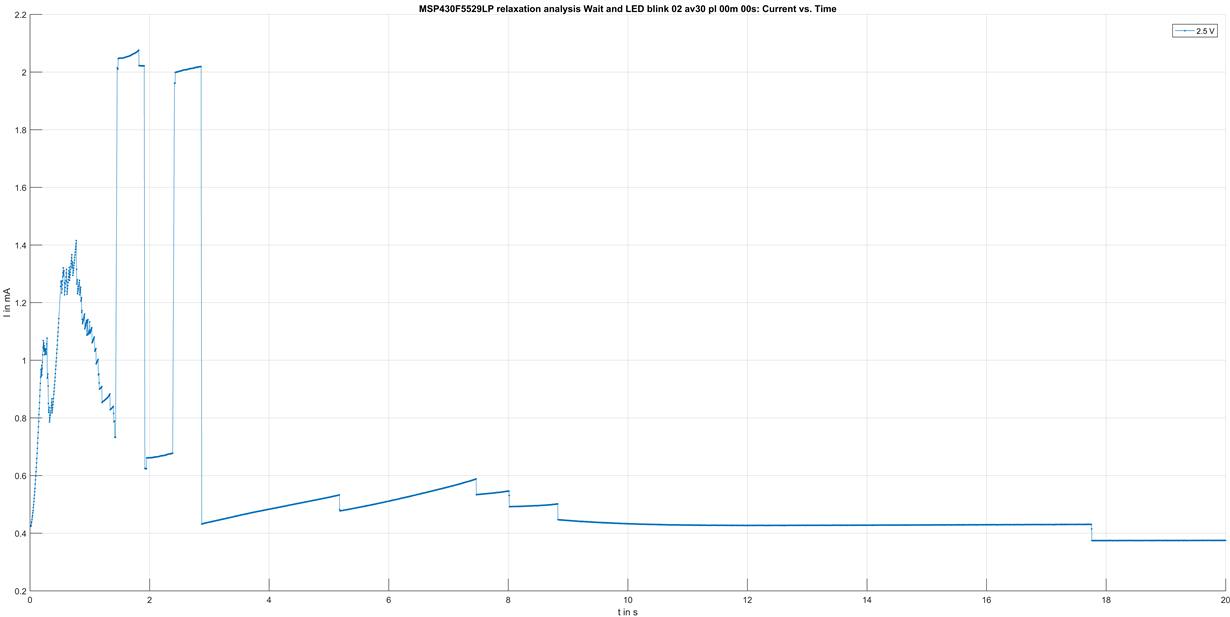
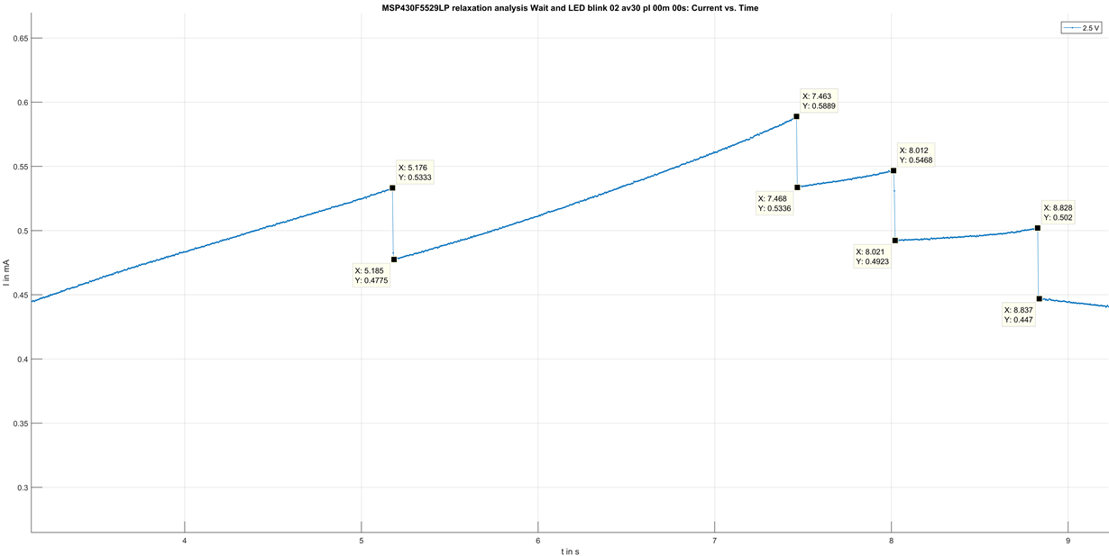
    thanks for the investgation. Here is an image of the current consumption @ 2.5V:

    The current jumps of the blue diagram vary a little.

    I zoomed the lower and higher area of the current consumption and marked some points:


    The following diagrams show the jumps caused by unterminated ports:

    Zoomed views with datatips:

    Best regards

    Martin

  • Hi Martin,

    I setup a test bench in our lab reproducing exactly the same behavior as you have observed. However I direcltly used the assembler code to have better control of the addresses and the register settings and my assumption was right it is a memory alignment problem! Adding 1 single nop to shift the 0.5s loop by 1 word and align it to 32 bit will make the difference in current consumption disappear.


    #include <msp430.h>

    ;-------------------------------------------------------------------------------
                ORG     08000h
    ;-------------------------------------------------------------------------------

    RESET       mov.w   #04C00h,SP         ; Initialize stackpointer
                mov.w   #WDTPW + WDTHOLD,&WDTCTL; Stop WDT   
                mov.b   #000h,&P1OUT
                mov.b   #0FFh,&P1DIR
                mov.b   #000h,&P2OUT
                mov.b   #0FFh,&P2DIR
                mov.b   #000h,&P3OUT
                mov.b   #0FFh,&P3DIR
                mov.b   #000h,&P4OUT
                mov.b   #0FFh,&P4DIR
                mov.b   #000h,&P5OUT
                mov.b   #0FFh,&P5DIR
                mov.b   #000h,&P6OUT
                mov.b   #0FFh,&P6DIR             
                mov.w   #000h,&PJOUT
                mov.w   #0FFh,&PJDIR            
               
                bis.B        #1,&P1OUT
                bic.B        #1,&P1OUT

                mova    #0x0100AE,PC    
               
                ORG     0100AEh
    test_loop
               PUSHM.A      #2,R14
               MOV.W        #0x108c,R13
               MOV.W        #0x0003,R14

    loop1s
               DEC.W        R13
               SBC.W        R14
               JNE          loop1s
               TST.W        R13
               JNE          loop1s
               POPM.A       #2,R14
               CLR.W        R15
               CMP.W        #4,R15
               JGE          end_loop
              
    for_loop
               PUSHM.A      #2,R14
               MOV.W        #0x2844,R13
               MOV.W       #1,R14
               nop                     ; this nop will align the 2nd loop to 32 bit and the behavior will disappear.

    loop0_5s
               DEC.W        R13
               SBC.W        R14
               JNE          loop0_5s
               TST.W        R13
               JNE          loop0_5s
               POPM.A       #2,R14
               NOP    
               XOR.B        #1,&P1OUT
               INC.W        R15
               CMP.W        #4,R15
               JL           for_loop
              
               PUSHM.A      #2,R14
               MOV.W        #0x108c,R13
               MOV.W        #0x0003,R14

    loop1s_2
               DEC.W        R13
               SBC.W        R14
               JNE          loop1s_2
               TST.W        R13
               JNE          loop1s_2
               POPM.A       #2,R14
               CLR.W        R15
               CMP.W        #4,R15
               JGE          end_loop          
     
    end_loop
                JMP         $

    ;-------------------------------------------------------------------------------
                      ; Interrupt Vectors
    ;-------------------------------------------------------------------------------
                ORG     0FFFEh                ; POR, ext. Reset
                DW      RESET
                END


    I attached a ppt file with the scope shots and some explanations:
    Measurement Results.pptx

    So if you can insert a nop (c_intrinc function) in your c code at the following location you difference in current consumption should disappear.

        for(i=0;i<4;i++)
        {

                      __no_operation
            __delay_cycles(500000); // 0.5 second delay; 0.1 second delay is 100000 cycles

            P1OUT^=(BIT0);    // toggle the led
        }
        __delay_cycles(1000000);
    This is a very good example we will use to improve our compiler with respect to memory alignment.
    Best regards,
    Dietmar
  • Martin,

    I meaured the current dynamically via 1 Ohm shunt with a gain of 2000 so if you would like to see the current you can divide the voltage of the current signal by 2000 and you have the current. Also please notice that I did not connected any load to P1.0 therefore you will not see the current jumps you've seen.
  • Hello Dietmar,

    this is a very interesting behaviour. I guess this could help to decrease the overall power consumption a little. The improvement could be introduced into the compiler which can lead to another pro for your company. The current saving is not much, but it shows that especially loops are predestined for such compiler optimizations if the compiler is set for maximum energy saving.

    If this effect is not already widely known I would like to publish our findings in a joint paper. What do you think? Maybe you can also propose an implementation in your Texas Instruments compiler to become more energy efficient.

    Best regards
    Martin Götz

**Attention** This is a public forum