Because of the Thanksgiving holiday in the U.S., TI E2E™ design support forum responses may be delayed from November 25 through December 2. Thank you for your patience.

This thread has been locked.

If you have a related question, please click the "Ask a related question" button in the top right corner. The newly created question will be automatically linked to this question.

MSP430G2553 SPI with MCP23S17

Other Parts Discussed in Thread: MSP430G2553

Hello! 

I'm having difficulties communicating with MCP23S17 I/O expander using SPI. I'm using IAR and Launchpad Rev.1.5 with MSP430G2553. Thing is, that attached leds don't even turn on. It even seems like master doesn't provide clock pulses or i'm missing something important. Maybe someone had experience with this I/O expander and with experienced eye could look what i'm missing. Unfortunately i don't have oscilloscope to look at outputs..

#include "msp430g2553.h"
	
// *** Global variables *** //
#define _CS	BIT5	//Set P1.3 as Chip Select

// *** Function prototypes *** //
void ConfigureSPI (void);	//Set up SPI communication

int main (void)
{
  // *** Set-up watchdogtimer and clock system *** //
  WDTCTL = WDTPW + WDTHOLD;		//Stop watchdog timer
  DCOCTL = 0;			//Select lovest DCOx and MODx settings
  BCSCTL1 = CALBC1_1MHZ;		//Set range
  DCOCTL = CALDCO_1MHZ;		//Set DCO step + modulation
  
  // *** Set up GPIO *** //
  P1OUT = 0x33;			//Turn pins LOW except P1.5(_CS) & P1.0
  P1DIR = 0xFD;			//Set Port 1 as OUTPUTS exc. P1.1
  
  ConfigureSPI();			//Configure MSP for SPI 
  while (1)
  {
    //Set A port to OUTPUTS
    P1OUT &= ~_CS;			//Set _CS LOW
    UCA0TXBUF = 0x40;		//Send Control Byte    
    while (!(IFG2 & UCA0TXIFG));    	//USCI_A0 TX buffer ready?
    UCA0TXBUF = 0x00;		//Access to IODIRA
    while (!(IFG2 & UCA0TXIFG));    	//USCI_A0 TX buffer ready?
    UCA0TXBUF = 0x00;		//Set to OUTPUTS
    while (!(IFG2 & UCA0RXIFG));    	//USCI_A0 TX buffer ready?
    P1OUT |= _CS;			//Set _CS HIGH
    __delay_cycles(10000);		//Simple delay
    //Send data to GPIOA address
    P1OUT &= ~_CS;			//Set _CS LOW
    UCA0TXBUF = 0x40;		//Send Control Byte    
    while (!(IFG2 & UCA0TXIFG));    	//USCI_A0 TX buffer ready?
    UCA0TXBUF = 0x09;		//Access to GPIOA 
    while (!(IFG2 & UCA0TXIFG));    	//USCI_A0 TX buffer ready?
    UCA0TXBUF = 0xFE;		//Turn ON OUTPUTS
    while (!(IFG2 & UCA0RXIFG));    	//USCI_A0 TX buffer ready?
    P1OUT |= _CS;			//Set _CS HIGH
    __delay_cycles(10000);		//Simple delay
   }
}
//Sub-programm for SPI setup
void ConfigureSPI(void)
{
  P1SEL |= BIT1 + BIT2 + BIT4;	//Set up pins
  P1SEL2 |= BIT1 + BIT2 + BIT4;	//Set up pins
  UCA0CTL1 = UCSWRST;
  UCA0CTL0 |= UCMSB + UCMST + UCSYNC;	//MSB first, Master mode, Synchronous mode (3-wire)
  UCA0CTL1 |= UCSSEL1;		//SMCLK    
  UCA0CTL1 &= ~UCSWRST;		//Release USCI for operation
}

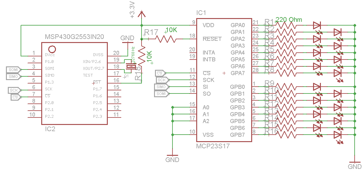
Simple schematic:

  • Hi Ivan!

    Just one thing I noticed when having a quick look at your code:

    Ivars K said:
    ...
    while (!(IFG2 & UCA0TXIFG));   	//USCI_A0 TX buffer ready?
    UCA0TXBUF = 0x00;               //Set to OUTPUTS
    while (!(IFG2 & UCA0RXIFG));    //USCI_A0 TX buffer ready?    <= PROBLEM!!!
    P1OUT |= _CS;                   //Set _CS HIGH
    ...

    This will not work as expected - CS will go high before everything was sent. The reason: UCA0RXIFG is already set at this point. Keep in mind that you already had a transmission before. This means that CS is set high before the current byte was transmitted. Try the following instead:

    P1OUT &= ~_CS;                  // Set _CS LOW
    IFG2 &= ~UCA0RXIFG              // Clear RX IFG
    UCA0TXBUF = 0x40;               // Send Control Byte    
    while( !(IFG2 & UCA0RXIFG) );   // Wait for transmission complete
    IFG2 &= ~UCA0RXIFG              // Clear RX IFG
    UCA0TXBUF = 0x00;               // Access to IODIRA
    while( !(IFG2 & UCA0RXIFG) );   // Wait for transmission complete
    IFG2 &= ~UCA0RXIFG              // Clear RX IFG
    UCA0TXBUF = 0x00;               // Set to OUTPUTS
    while( !(IFG2 & UCA0RXIFG) );   // Wait for transmission complete
    P1OUT |= _CS;                   // Set _CS HIGH

    Same for the second part. Of course I did not check if the command sequence for the slave is right in general.

    You should add some decoupling capacitors to the supply pins of the ICs. For example 10µ in parallel with 100n. I don't know the recommended circuitry for the IO expander's reset pin, but the MSP should get an additional small capacitor from RST to GND. TI recommends a 47k resistor from RST to Vcc and a 2.2nF capacitor from RST to GND.

    Dennis

  • Hi, Dennis!

    Thank You for reply. Actually You pointed my mistake here:

    ...
    UCA0TXBUF = 0x00;       //Set to OUTPUTS
    while (!(IFG2 & UCA0RXIFG));        //USCI_A0 TX buffer ready? -MY MISTAKE
    P1OUT |= _CS;           //Set _CS HIGH
    ...

    I needed to check TXIFG because I send data and need to make sure that they are sent before next  TXBUF writing. Reading is a different process. MSP is put in Launchpad so everything with bypass capacitors are good. But MCP23S17 is on breadboard and I added some capacitors at Vdd and RST pin. One important thing i just found out in MCP specs that for  SCLK setting I must set clock phase bit UCCKPH in UCA0CTL0 register. As for now at least attached leds ar turning on and I can keep working further. Thank You.

  • Hi Ivars!

    Ivars K said:
    I needed to check TXIFG because I send data and need to make sure that they are sent before next  TXBUF writing.

    Well, actually the TXIFG is not set when the previous byte was sent. It is set when a byte was moved from the TX buffer to the TX shift register and the TX buffer is free for the next byte. This is often a problem when people deassert CS after the TXIFG was set. You at least polled the RXIFG at the last transmission, but this still does not ensure that it will trigger after the correct byte even if it was cleared before.

    Imagine this:

    There is currently no activity on the USCI module and you place a byte into the TX buffer. This is forwarded to the TX shift register, TXIFG is set and you can place the next byte into the TX buffer while the previous one is transmitted in the background. TXIFG is cleared at the moment. Now the transmission of the first byte has finished, the second byte is moved from the TX buffer to the TX shift register, the TX buffer is free and the TXIFG is set. You now clear the RXIFG and place a new byte in the TX buffer. Remember that there is still the transmission of the second byte in the background. In your code you now poll for RXIFG. When the second byte has been transmitted completely, it will set RXIFG (a transmission is always a reception as well) and the third byte is now moved from the TX buffer to the TX shift register, also setting TXIFG again. Unfortunately you just polled for RXIFG which got set after the second byte, so your code continues and sets CS high while the third byte is still transmitting. This can happen. You may be lucky if timing is on your side, but this depends on transmission speed and other things. It can also be unpredictable.

    So when only polling for RXIFG that was cleared before every byte you definitely know the transmission has finished. This is less efficient, of course - you are wasting a bit of time because you do not fill the TX buffer with a new byte while there is another transmission active. But it is safe. This is why I made this suggestion. Or have a look at the most effective interrupt driven mechanisms.

    Dennis

  • Hi Dennis!

    You are right about this! That is very important nuance. My timing for now was just lucky. I also found a statement in family's guide about TXIFG set. Your suggestion works very good with safer data transmitting.  I have one question - is it safe alternative for data transmitting/receiving  approach using code below?

    P1OUT &= ~_CS;		//Set _CS LOW
    UCA0TXBUF = 0x40;		//Send Control Byte  (Write)  
    while (!(UCBUSY & UCA0STAT));	//Are TX/RX operation in progress?
    UCA0TXBUF = 0x12;		//Access to GPIOA 
    while (!(UCBUSY & UCA0STAT));	//Are TX/RX operation in progress?
    UCA0TXBUF = data;		//Turn ON OUTPUTS
    while (!(UCBUSY & UCA0STAT));	//Are TX/RX operation in progress?
    P1OUT |= _CS;		//Set _CS HIGH

**Attention** This is a public forum