This thread has been locked.

If you have a related question, please click the "Ask a related question" button in the top right corner. The newly created question will be automatically linked to this question.

MSP-GANG: ERROR #23 with M430F5418/5418A

Part Number: MSP-GANG

Hello!
I have a problem with programming MSP430 microcontrollers with the MSP-GANG programmer.

I have instruments based on M430F5418/5418A MCU's. Marking of microcontrollers M430F5418 REV N and M430F5418A REV F.

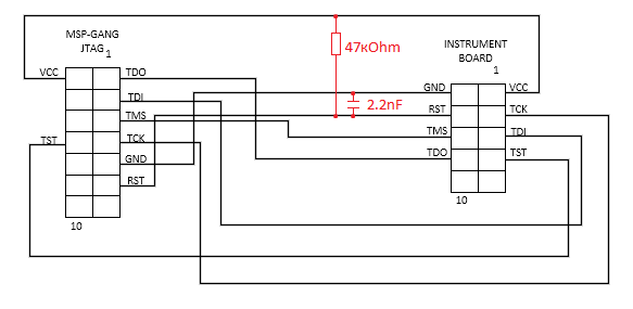
The devices have a programming connector. I'm connected to the connector as indicated on the diagram.

The corresponding type of microcontroller is selected in the MSP Gang Programmer Tool, but an initialization error occurs when trying to read or write the program.

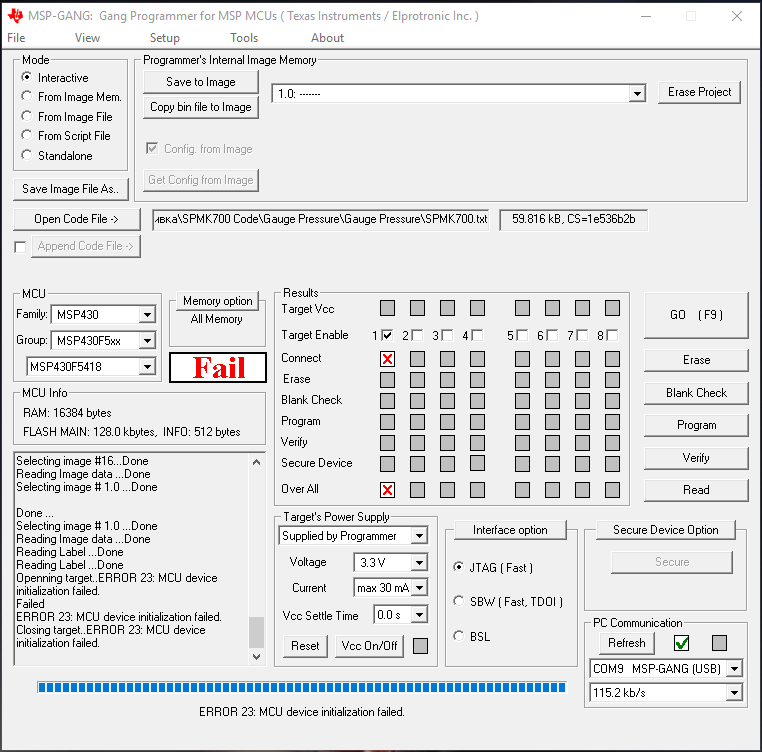
Please, tell me, what could be the cause of the error.
Tell me if you need more information.

  • Hi Andrey,

    It looks like the test pin in your diagram might be in the wrong location. Looking at the schematic for the MSP-GANG User's Guide it shows the test pin across from the TCK pin.

    If that doesn't solve your problem, you might try programming another JTAG device with the MSP-GANG from the same and different ports to see if the programmer is having issues as well as testing the continuity of the cables you're using to make sure there isn't a break in one. You might also want to try changing the Interface Option setting from fast to a slower setting.

    Regards,

    Ryan

  • Hi Ryan,

    Thanks for you answer.
    Sorry, I made a mistake on the diagram, the connection was made according to the instructions.


    The adapter is working, I tested it on a device with M430F449 with the same connector for programming.
    The change in the speed of the JTAG interface did not work.

    If you have any other ideas, I will be very grateful for your help.

  • Hi Andrey,

    You may also want to take a look at the MSP430F418 Device Erratasheet and MSP430F418A Device Erratasheet. They give a list of hardware bugs and workarounds related to different revisions of the MCU in your instruments.

    What firmware version is on the MSP-GANG you are using? According to the erratasheets, it looks like MSP-GANG might have trouble programming the MCU revisions you are using if the firmware is older than v1.2.3.0. You can check by going to Tools >> Gang API Firmware Update at the top of the MSP-GANG Programmer GUI.

    Other than that, you could also try testing the continuity between your instrument board connector and the MCU pins to make sure they are connected as expected.

    Regards,

    Ryan

  • Hi Ryan,

    The firmware version has been updated to 01.02.08.00.
    Connections between the connector and the MCU checked. All connections are intact.

      Instrument connector MCU
    VCC 1 11, 16, 31, 51, 67
    GND 2 12, 15, 30, 50
    TCK 3 75
    RST 4 76
    TDI 5 73
    TMS 6 74
    TST 7 71
    TDO 8 72

    The device was programmed in the factory using the LSD-PRGS430-IIIA programmer. Now we need to program the device to fix some errors, but I can not do it with MSP-GANG programmer because of an initialization error.
    It's funny that a third-party programmer works with TI MCU more correctly than a proprietary one.

    I'll look at the MSP430F418 Device Erratasheet and MSP430F418A Device Erratasheetbut I'm inclined to the fact that the problem with the programmer.

  • Hi Andrey,

    On your RST line, do you have a 47 kOhm pullup resistor and 2.2 nF capacitor connected between RST and ground? Having a capacitor that is too large can make the reset response time too slow for the MSP-GANG. Do you have any other passive components on these lines? The connection should match Figure 2-1 in the MSP430 Hardware Tools User's Guide.

    How long is the total cable length between the MCU and the MSP-GANG for each of the lines? The total signal path length should not exceed 50 cm.

    Regards,

    Ryan

  • Hi Ryan,

    There are no passive components on the board. I added them to the adapter and removed the length of the connecting lines (about 25 cm considering the cable of the programmer). Unfortunately, this did not give a positive result.

  • Hi Andrey,

    Are you still having issues programming the instrument?

    Is it possible you can provide a schematic of your instrument showing the connections and components with their values between the MCU and the connector as well as the components you added to the connector? Are you able to use a multimeter to measure the voltage on the reset pin of the MCU to make sure it is at 3.3V?

    Thanks,
    Ryan
  • HI Ryan,

    Sorry for the long answer.

    I finally solved the problem.

    I added a 47 kΩ resistor with a 2.2 nF capacitor in the RST circuit, but that did not work.

    I ripped the microcontroller's power circuit from the rest of the board, removing one of the elements, and only then did the microcontroller correctly initialize.

    Apparently the switching-on of some elements on the board interfered with the initialization process.

    Thank you for your help.

**Attention** This is a public forum