This thread has been locked.

If you have a related question, please click the "Ask a related question" button in the top right corner. The newly created question will be automatically linked to this question.

MSP430F67791A: Purpose for EEPROM in TIDM-THDREADING design

Other Parts Discussed in Thread: MSP430F67791A, MSP430F6779A, EVM430-F6779, MSP430F6779, TIDM-AUX-MODULE, MSP-FETJames:

Work underway on the MSP430F67791A design using the TIDM reference design. Quick question. What is the EEPROM in the design being used for?

Thanks

Dan
  • Hello Dan,

    I created a new thread, since this question is different than your initial question in the thread below. Please keep this in mind for future questions.

    To answer your question, the EEPROM is used to store multi-rate schedules related to different time slots, holidays, cutoff dates, daily peaks, etc. Multi-rate features vary considerably. This software provides sophisticated multi-rate features, for single and 3-phase meters. It does this with very modest Flash or RAM usage. The software can store all schedules, and recorded usage, in an external EEPROM. However, the schedules can be stored in a section of the MCU's Flash.

    For more details about the EEPROM, I would encourage you to search for "EEPROM" in the source code and header files. It appears that the external EEPROM support is disabled by default in the 'emeter.h' file. Other helpful files include 'emeter-3ph-neutral-6779.h', 'iiceeprom.c', 'emeter-structs.h', 'emeter-toolkit-custom.h', and 'emeter-multirate.h'.

    /* Many data logging requirements can be met by using only the MSP430's
       info memory. If an external serial EEPROM is needed for more
       complex requirements, this switch will enable an interface to
       I2C type serial EEPROMs. Basic routines to driver these EEPROMs are
       included in the toolkit. Routines to actually store and retrieve
       information are left to the meter designer. */
    #undef EXTERNAL_EEPROM_SUPPORT

    Regards,

    James

    MSP Customer Applications

  • James:

    Thanks. We will provide the footprint and determine in the future whether or not to populate/use it.

    Dan
  • Sounds good!

    Regards,

    James

    MSP Customer Applications
  • James, One more.

    On page www.ti.com/.../evm430-f6779 we saw that Code Composer is listed as a "Related Product" "Development Tool". In reading other docs, looks like the code IDE is IAR MSP430. Please advise. We do not have IAR for MSP430 and would prefer to not have to part with $3000+ just for this project development.

    Please advise. Thanks Dan
  • CCS is not currently supported, but we're trying to release this support at the end of this quarter.

    Regards,

    James

    MSP Customer Applications
  • James,

    Thanks. Good news if the release is done when you indicated above. Can you give me the odds?

    Also you closed the previous thread. In detailed examination of the firmware we have questions on whether we can do what we ideally want. There seems to be some low level code that we don't have access to that might be needed.

    Can you address the following?

    There have 7 A/Ds on the meter chip. Right now in the 3 phase application they are assigned as 4 CTs and 3 Voltage Inputs.

    "Ideally" we really want to use 5 CTs and 2 voltage inputs 120V L1 and 120V L2.

    3 of the CTs will be on L1 and 2 Cts on L2


    With the current firmware:

    Will we be able to assign one of the 3 A/Ds that measures voltage to instead be used for a 5th CT?

    Will we be able to read registers to get KW independently for each of the 4 CTs (and hopefully a 5th CT) ?

    Will we be able to read registers and get amps for each of the 4 CTs (and hopefully a 5th CT)?

    Will we be able to read registers and get voltage for both L1 and L2?

    Thanks

    Dan
  • Hello,

    Daniel Flohr said:
    Thanks. Good news if the release is done when you indicated above. Can you give me the odds?

    We're working hard on this, and it's not been an easy task. Besides CCS support, another goal is to make everything easier to use. I'll keep you posted and reach out to you directly when it's done.

    Daniel Flohr said:
    With the current firmware:

    Will we be able to assign one of the 3 A/Ds that measures voltage to instead be used for a 5th CT?

    Will we be able to read registers to get KW independently for each of the 4 CTs (and hopefully a 5th CT) ?

    Will we be able to read registers and get amps for each of the 4 CTs (and hopefully a 5th CT)?

    Will we be able to read registers and get voltage for both L1 and L2?

    What you're describing is possible but it would take some work. Can you change the firmware to do this? Sure. Does the MSP430F6779A support 7 Sigma Delta ADC differential input channels? Yes. To get started, I would recommend purchasing the EVM430-F6779, getting familiar with the code and the code, and start modifying the code to support 2 voltages instead of 3, understanding how the current channels are set up, etc.

    Another development option would be to use the MSP430F6779A with a target board. I've used a signal generator to simulate inputs from a CT or shunt to the differential inputs successfully when I couldn't get into the lab.

    Regards,

    James

    MSP Customer Applications

  • James:

    Thanks for the CCS update.

    Getting concerned about the risks of having to modify 3 phase meter code to something different that the code wasn't designed for.

    Instead, is there a 2 phase meter solution for a US meter where there is 240V split with a neutral? If so, does it have the phase angle calculator to determine which direction the power is going through the CT? In this case, we would use two of the meter ICs to watch the 4 CTs.

    Sorry for the questions. It's a big project and we want to get the right solution from the start.

    Dan
  • Hello,

    Thanks for the additional details, and I understand your concern. Unfortunately, we don't have source code that matches your application exactly. However, it's a good start and looking at the 'metrology-template.h' file, you can change the number of phases to two (#define NUM_PHASES  2), the number of voltage channels to two (#define VOLTAGE_CHANNELS  2), and then the number of current channels to four (#define CURRENT_CHANNELS  4). From my experience with the code, there's logic that should automatically make changes to structures, etc. for the different phase and channel configuration. Next, you'd want to define which channels are doing what (e.g. Channel 0 is Line 1, Channel 1 is Line 2, Channel 2 is Current 1, etc.). The channel allocation is done in the 'metrology-template.h' file (see code below).

    /*! ADC channel allocation */
    #define PHASE_1_VOLTAGE_ADC_CHANNEL                 0
    #define PHASE_1_CURRENT_ADC_CHANNEL                 4
    #define PHASE_2_VOLTAGE_ADC_CHANNEL                 1
    #define PHASE_2_CURRENT_ADC_CHANNEL                 5
    #define PHASE_3_VOLTAGE_ADC_CHANNEL                 2
    #define PHASE_3_CURRENT_ADC_CHANNEL                 6
    #define NEUTRAL_CURRENT_ADC_CHANNEL                 3

    I'm confident that the MSP430F6779(A) can meet your requirements since it supports 7 channels. Again, I would still recommend purchasing the EVM430-F6779, getting familiar with the code, and then modifying the channel configurations from three to two.

    If you aren't able to purchase an EVM yet, perhaps getting the target development board for the MSP430F6779(A) and inputting differential AC signals (below the Full Scale Range obviously) using signal generators will help. Here, you could create phase shifts between the channels to see how the phase angles are measured.

    Regards,

    James

    MSP Customer Applications

  • Hi James: Any update on CCS support for the EVM MSP430F6779 ? It's "end of this quarter" :) Dan
  • Hello Daniel,

    Thanks for your continued interest. We have a tentative release date set as Apr 6th and are doing our best to hit that date. Currently, I'm doing extensive validation testing on the new library while some other features are getting implemented. You will not be disappointed, and I will keep you posted.

    Regards,

    James

    MSP Customer Applications
  • James: Great news. While the use case we have is a bit different, I believe there is a high value opportunity in getting the code to support not just 3 phase metering that it does today. Setting it up to be two 240VAC split phase meters in one for US market makes sense, especially with the growth in electric vehicles. Dual meters would allow separate metering of home and EV charger. In Cali, two meters are often used for the EV charger.(Expensive) In GA where I am (I buy power for my EV 11PM to 7AM for $.01/KWh) it's a single meter. Good for us but not good for power company since we schedule to run as much of house loads after 11PM.

    For what it's worth. Hope you go there :) Dan
  • Hi James: Any Code Composer porting update for meter code ? Thanks

    Dan
  • Hello Dan,

    Thanks for your patience.

    I’m happy to inform you that the official software release for the new Energy Measurement Design Center and Software Library is available on TI.com. It supports CCS and includes documentation and Design Center examples for the supported EVMs. Please download and install the release from the following link:

    Let me know if you have any questions.

    Regards,

    James

    MSP Customer Applications

  • James:

    Great, Thanks!   Don't think the files have been posted yet with the link above :     http://www.ti.com/tool/download/MSP430-ENERGY-MEASUREMENT

    Will keep trying.

    Dan

  • Hello Dan,

    That's strange. Can you try a different browser? Can you see anything on the page? I've been able to access the page outside of our network, so I'm not sure why the files can't be accessed. Please keep me posted.

    Regards,

    James

    MSP Customer Applications
  • James: very odd. Multiple browsers, multiple computers within LAN. No good. Laptop tethered to Verizon phone, No good. Note 8 with Dolphin Browser, finally got it.

    At first quick glance if I understand what you did with the GUI, AWESOME.

    Thanks

    Dan
  • Hello Dan,

    I'm glad you were able to access it. For the other browsers, perhaps you could try clearing your browsing history and cookies. We are very excited to finally get this release out to the web. It's been a lot of work and we look forward to hearing how it helps users and their feedback.

    Regards,

    James

    MSP Customer Applications
  • Hi James:

    Now that we have the development board operational  have begun our layout of our version.    It will be very stripped down (no display for example.)   We would like to use the 100 PIN version of 6779A.  We'll map the IO exactly the same as reference design.  Any issue with using the same firmware base?

    Also, can you assist or can you suggest where to post hardware questions particularly about all of the power supply requirements.  It is a bit confusing from the datasheet regarding  DVCC, AVCC, AUXVCC1, AUXVCC2, AUXVCC3, VASYS1, VASYS2, DVSYS1, DVSYS2.  We will have a single 3.4 VDC supply for the whole board. 

    Thanks

    Dan

  • Hello,

    Your last post seems to have been cut off. Can you re-post? Thanks.

    Regards,

    James

    MSP Customer Applications
  • Hi James:

    Now that we have the development board operational have begun our layout of our version. It will be very stripped down (no display for example.) We would like to use the 100 PIN version of 6779A. We'll map the IO exactly the same as reference design. Any issue with using the same firmware base?


    Thanks

    Dan
  • Hello Dan,

    Sounds like you're making great progress! I believe that the EVM430-F6779 does feature the 100-pin version of the F6779(A), so as long as you make all the same connections, the same firmware base should work. I'm glad that you're using the A-version and not the F6779, since it has several improvements.

    Be mindful of the AUX1, AUX2, and AUX3 connections. I would recommend referring to the Battery Management and Auxiliary Power Supply Options for E-Meters TI Design (TIDM-AUX-MODULE) and its user's guide for some helpful examples for making those connections.

    Has the new EMDC tool been helpful on the software development front? If you have any feedback, let me know!

    EDIT: The EVM430-F6779 features the 128-pin version, not the 100-pin version.

    Regards,

    James

    MSP Customer Applications

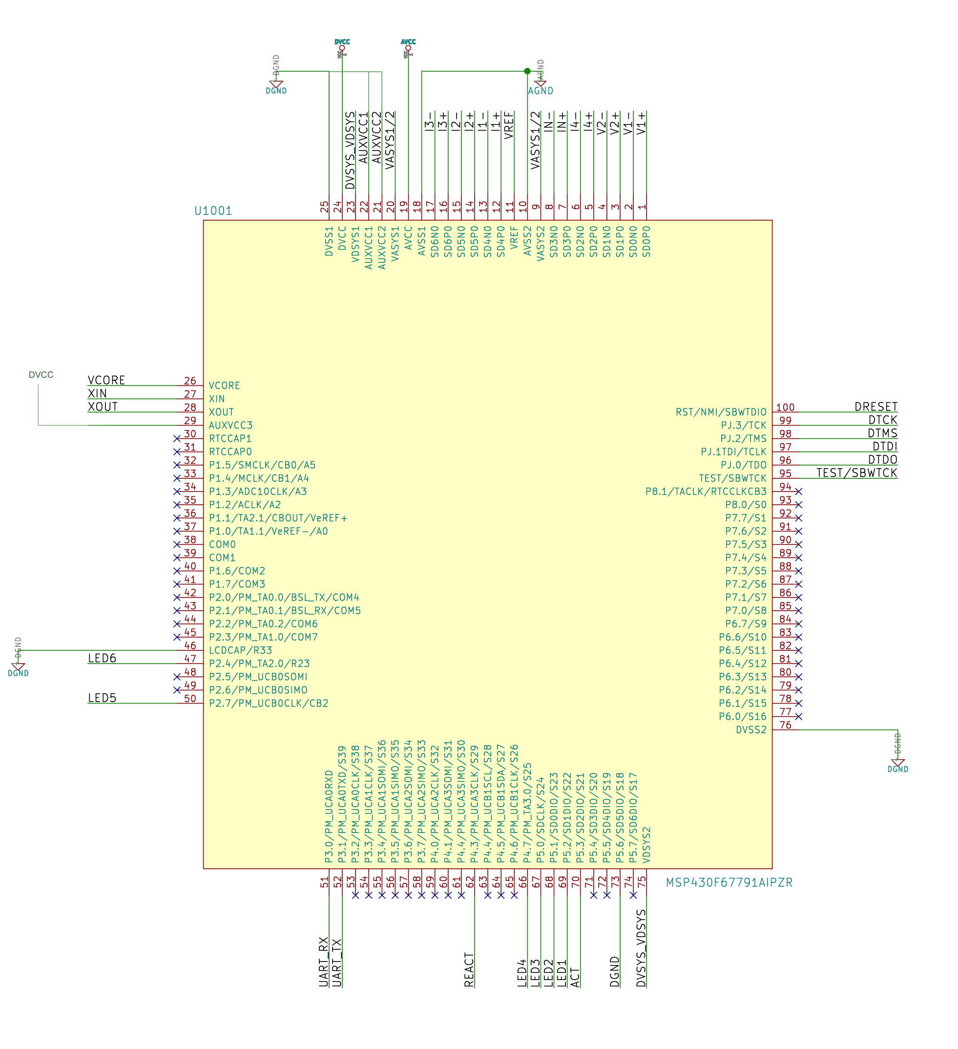
  •  James,   Attached is a drawing showing our connections to the 100 pin  6779A.   Very reduced set of connections.  Want to make sure we get this right.   Can it be reviewed?   Are there any of the (many) unused pins that need special terminations?  Took care on the AUXVCCs  and LCDCAP/R33.   Thanks  Dan

  • Hello Dan,

    First, let me point out that I was wrong in my earlier post. The EVM430-F6779 uses the 128-pin version, not the 100-pin version. Looking at your connections, nothing wrong jumps out at me. For the many unused pins, they look fine, but you'll want to switch them to port function, output direction in your code. See Table 4-5 in the datasheet for more details. You'll want to make sure AGND and DGND get connected too.

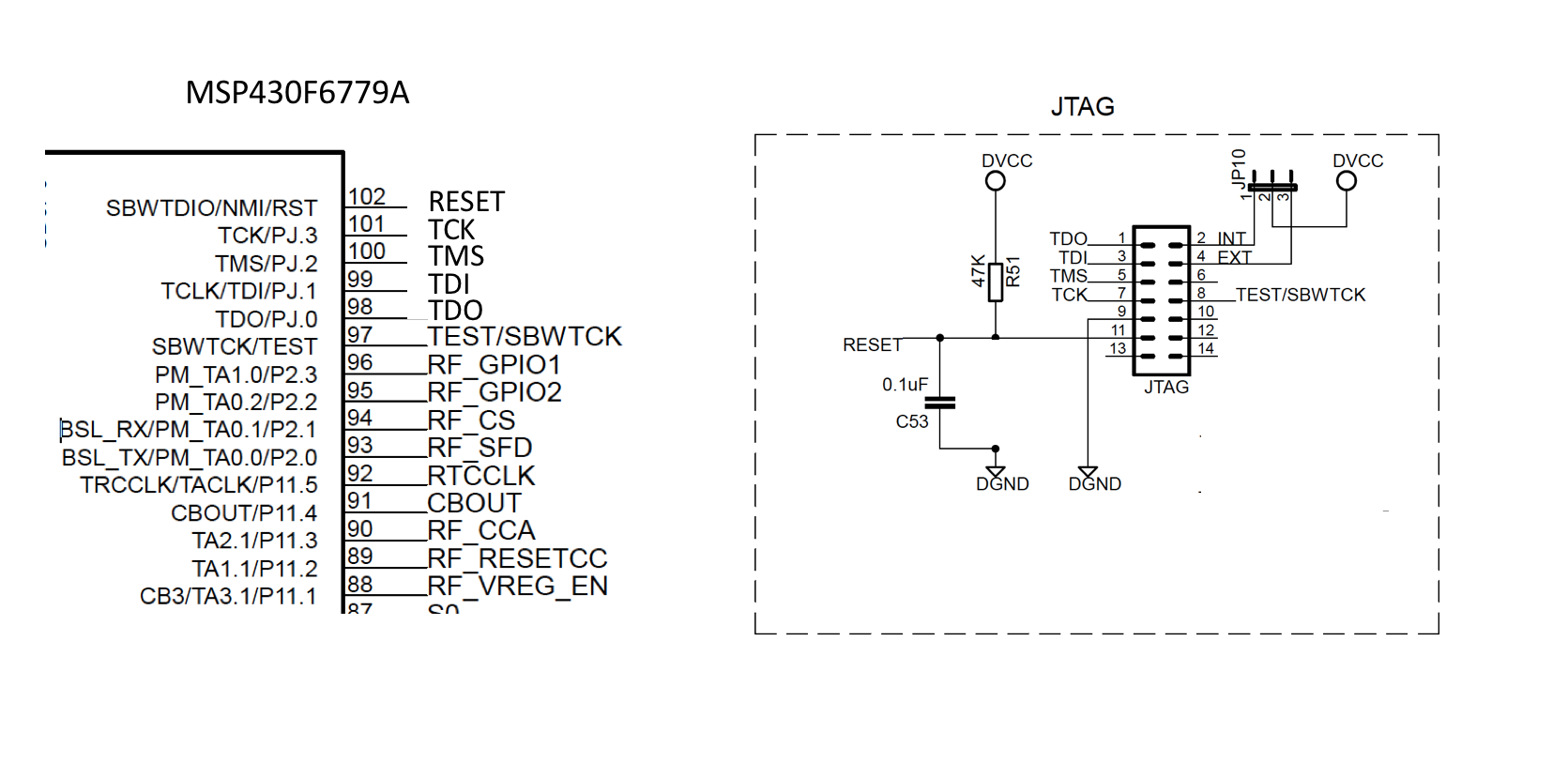
    Next, I would be sure to add the recommended capacitors for DVCC/AVCC (called CVCC), VDSYS1/VDSYS2/VASYS1/VASYS2 (called CVSYS), VCORE (called CVCORE), and AUXVCC3 (called CAUX3) pins. Also, make sure to add load capacitors for the external oscillator, XT1. Overall, refer to the schematic for the EVM430-F6779 as a reference for what to keep as you step back a level from the MSP430 connections and focus on the next level. For example, the schematic for the EVM430-F6779 includes sections like "Analog Power" and "Digital Power" which includes the recommended capacitors but also other smaller decoupling capacitors for better noise immunity. Finally, pay attention to the JTAG circuitry. The schematic has a "JTAG" section, but it features headers for alternating between 2-wire and 4-wire JTAG connections, so it may not be easy to replicate on your design. Refer to Figure 2-1 in the MSP430 Hardware Tools User's Guide for more details.

    Hope this helps!

    Regards,

    James

    MSP Customer Applications

  • James:

    Meter layout well underway.  We are following your notes above and paying attention to the reference design.

    Few of questions.

    1. Reference design says that the 12 pF Crystal caps are DNP.  You state above to populate them.   Please clarify.  ( Is watch Xtal even 100% required. Device will never go into low power mode.)

    2. The reference design uses two pairs of three  0 Ohm jumpers to connect AGND and DGND.   Any guidance on that?

    3. We intend to connect 4 wire JTAG exactly as shown in the reference without the jumpers as per this.   Trust it's OK

    Thanks

    Dan


  • Hello Dan,

    I'm sorry for the delayed response. Let me address your questions.

    Daniel Flohr said:
    Meter layout well underway.  We are following your notes above and paying attention to the reference design.

    Excellent! Nice work.

    Daniel Flohr said:
    1. Reference design says that the 12 pF Crystal caps are DNP.  You state above to populate them.   Please clarify.  ( Is watch Xtal even 100% required. Device will never go into low power mode.)

    I would populate them. For some reason, the schematics in the reference design show these crystal load capacitors as DNP, but on all the EVMs that I have, they are there. Although I'm not the author, I'll submit a request to have this changed in the documentation. Basically, you can use the internal crystal load capacitors, but they are implemented in silicon and may not be as precise (which is important) as high tolerant, high precision load capacitors. Depending on which crystal that you select, the internal capacitors may not be adequate for the required effective load capacitance for the selected crystal (rare but possible).

    Daniel Flohr said:
    2. The reference design uses two pairs of three  0 Ohm jumpers to connect AGND and DGND.   Any guidance on that?

    Most likely, this was done to implement a star ground to minimize noise between the analog and digital grounds. If any noise needed to be mitigated, then you could easily replace the 0 Ohm resistors with inductors instead. Check out these valuable resources about grounding techniques in mixed-signal systems.

    Grounding in mixed-signal systems demystified, Part 1

    Grounding in mixed-signal systems demystified, Part 2

    Daniel Flohr said:
    3. We intend to connect 4 wire JTAG exactly as shown in the reference without the jumpers as per this.   Trust it's OK

    Since you're removing the jumpers, just make sure that you connect Pin 4 (EXT) of the JTAG connector to DVCC. On the EVM, Pin 2 allows the MSP-FET to supply DVCC when a jumper is across Pins 1 and 2 of JP10. You can see that the connections are very similar to what we recommend in Figure 2-1 in the MSP430 Hardware Tools User's Guide.

    I hope this helps!

    Regards,

    James

    MSP Customer Applications

  • Daniel Flohr said:
    Is watch Xtal even 100% required. Device will never go into low power mode.

    I missed this. Yes, I would highly recommend using XT1. We use it as the FLL reference clock for the DCO, and it provides more stability than using the internal REFO as the FLL reference clock.

    Regards,

    James

    MSP Customer Applications

  • James:

    Perfect thank you.

    Dan

  • James:

    One more. On the Current Transformer input circuits, after the diodes and TVS, there are two series 0 Ohm/L jumpers for each CT.

    Any experience or guidance here. Jumper or inductor/ferrite etc?

    Thanks

    Dan
  • Hello Dan,

    These 0 Ohm jumpers are just placeholders for the optional EMI ferrite beads/suppressant inductors. If you have room on your test PCB, I would recommend keeping them, in case you need to filter out certain noise/frequencies during your testing. For your final product PCB, it'll be up to you whether or not to include them. Hope this helps.

    Regards,

    James

    MSP Customer Applications
  • Perfect thanks

**Attention** This is a public forum