This thread has been locked.

If you have a related question, please click the "Ask a related question" button in the top right corner. The newly created question will be automatically linked to this question.

CCS/MSP430FR2310: I2C at 400 kHz sourced from SMCLK, MSP430 is Master

Part Number: MSP430FR2310

Tool/software: Code Composer Studio

Hello,

What I thought would be a very simple task has now delayed a project by two weeks, and although I think that I have identified the problem, I would like expert advice.

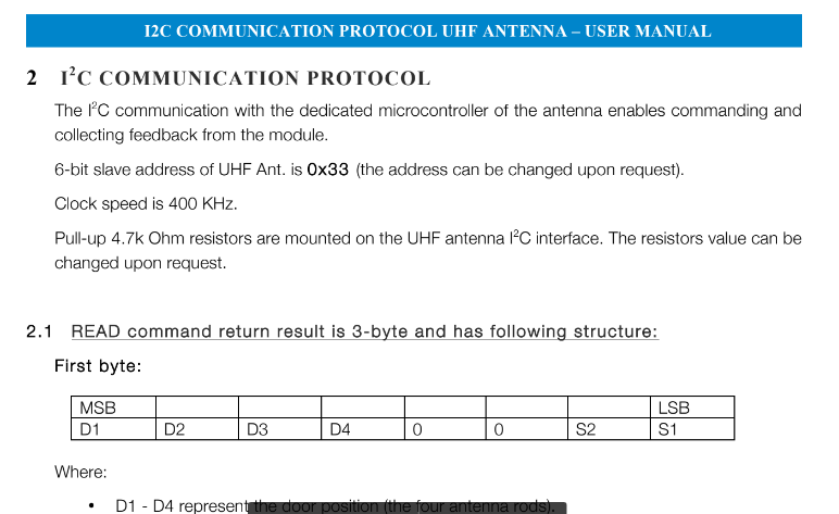
The msp430 is used for a single task when the system is starting up. It delays 30 seconds, then sends 0x1F to an i2c slave at 0x33 at 400 kHz. That's it.

I have read the clock system and i2c sections of the user manual and don't believe that I am missing anything, and have looked through the code examples [here]. 

I tried to stay as close to the examples as possible. My approach was as follows:

1st, I followed one of the examples,  msp430fr231x_CS_01.c "Configure MCLK for 8MHz sourced from DCO." to set DCO to 2.4 kHz (although I am not sure that it wan't taken as 2 kHz)

Then I used CSCTL5 to set MCLK to 2.4 MHz and SMCLK to 400 kHz. Next I configure the I2C pins, then for testing purposed transmit 0x1F to 0x33 every 3 seconds.

I copied-and pasted the interrupt handling and the trimming function from the examples and modified a few parameters.

I have verified that the scl signal exists with an oscilloscope, but I have used an "aardvark" i2c testing device from total phase in addition to a testing tool provided by the manufacturer of the slave device, and neither actually recognizes that information is being sent. Does the code below match the task? Is there anything in the description above that suggests another mistake?

Thanks in advance,

#include <msp430.h> 


void Software_Trim();                       // Software Trim to get the best DCOFTRIM value
unsigned char TXData =0x1F;
unsigned char TXByteCtr;

#define MCLK_FREQ_MHZ 2.4                    // MCLK = 2.4MHz


int main(void)
{
	WDTCTL = WDTPW | WDTHOLD;	    // stop watchdog timer

    __bis_SR_register(SCG0);                // disable FLL
    CSCTL3 |= SELREF__REFOCLK;              // Set REFO as FLL reference source
    CSCTL1 = DCOFTRIMEN_1 | DCOFTRIM0 | DCOFTRIM1 | DCORSEL_3;// DCOFTRIM=3, DCO Range = 2.4MHz
    CSCTL2 = FLLD_0 + 243;                  // DCODIV = 2.4MHz
    __delay_cycles(3);
    __bic_SR_register(SCG0);                // enable FLL
    Software_Trim();                        // Software Trim to get the best DCOFTRIM value


    CSCTL4 = SELMS__DCOCLKDIV | SELA__REFOCLK; // set default REFO(~32768Hz) as ACLK source, ACLK = 32768Hz
                                            // default DCODIV as MCLK and SMCLK source
    
    CSCTL5 |= DIVM_0 | DIVS_3;              // MCLK = XT1CLK = 2.4MHZ,
                                            // SMCLK = MCLK/2 = 0.4MHz = 400 kHz

	// Configure I2C Pins
	P1SEL0 |= BIT2 | BIT3;       //I2C pins

	// Disable the GPIO power-on default high-impedance mode
	// to activate previously configured port settings
	PM5CTL0 &= ~LOCKLPM5;

    // Configure USCI_B0 for I2C mode
    UCB0CTLW0 |= UCSWRST;                             // put eUSCI_B in reset state
    UCB0CTLW0 |= UCMODE_3 | UCMST;                    // I2C master mode, SMCLK
    UCB0BRW = 0x8;                                    // baudrate = SMCLK / 8
    UCB0CTLW0 &=~ UCSWRST;                            // clear reset register
    UCB0IE |= UCTXIE0 | UCNACKIE;                     // transmit and NACK interrupt enable

while(1){
    //Delay for 3s
    __delay_cycles(300000); //30000000

    //Deployment Algorithm 1 for all 4 antennas
    UCB0I2CSA = 0x33;                                 // configure slave address to 0x33
    TXByteCtr = 2;                                    // Load TX byte counter
    while (UCB0CTLW0 & UCTXSTP);                      // Ensure stop condition got sent
    UCB0CTLW0 |= UCTR | UCTXSTT;                      // I2C TX, start condition

    __bis_SR_register(LPM0_bits | GIE);               // Enter LPM0 w/ interrupts
}
    //return 0;
}

#if defined(__TI_COMPILER_VERSION__) || defined(__IAR_SYSTEMS_ICC__)
#pragma vector = USCI_B0_VECTOR
__interrupt void USCIB0_ISR(void)
#elif defined(__GNUC__)
void __attribute__ ((interrupt(USCI_B0_VECTOR))) USCIB0_ISR (void)
#else
#error Compiler not supported!
#endif
{
  switch(__even_in_range(UCB0IV, USCI_I2C_UCBIT9IFG))
  {
    case USCI_NONE: break;                  // Vector 0: No interrupts
    case USCI_I2C_UCALIFG: break;           // Vector 2: ALIFG
    case USCI_I2C_UCNACKIFG: break;         // Vector 4: NACKIFG
    case USCI_I2C_UCSTTIFG: break;          // Vector 6: STTIFG
    case USCI_I2C_UCSTPIFG:                 // Vector 8: STPIFG
      TXData = 0;
      UCB0IFG &= ~UCSTPIFG;                 // Clear stop condition int flag
      break;
    case USCI_I2C_UCRXIFG3: break;          // Vector 10: RXIFG3
    case USCI_I2C_UCTXIFG3: break;          // Vector 14: TXIFG3
    case USCI_I2C_UCRXIFG2: break;          // Vector 16: RXIFG2
    case USCI_I2C_UCTXIFG2: break;          // Vector 18: TXIFG2
    case USCI_I2C_UCRXIFG1: break;          // Vector 20: RXIFG1
    case USCI_I2C_UCTXIFG1: break;          // Vector 22: TXIFG1
    case USCI_I2C_UCRXIFG0: break;          // Vector 24: RXIFG0
    case USCI_I2C_UCTXIFG0:
       UCB0TXBUF = TXData++;
       break;                               // Vector 26: TXIFG0
    case USCI_I2C_UCBCNTIFG: break;         // Vector 28: BCNTIFG
    case USCI_I2C_UCCLTOIFG: break;         // Vector 30: clock low timeout
    case USCI_I2C_UCBIT9IFG: break;         // Vector 32: 9th bit
    default: break;
  }
}

void Software_Trim()
{
    unsigned int oldDcoTap = 0xffff;
    unsigned int newDcoTap = 0xffff;
    unsigned int newDcoDelta = 0xffff;
    unsigned int bestDcoDelta = 0xffff;
    unsigned int csCtl0Copy = 0;
    unsigned int csCtl1Copy = 0;
    unsigned int csCtl0Read = 0;
    unsigned int csCtl1Read = 0;
    unsigned int dcoFreqTrim = 3;
    unsigned char endLoop = 0;

    do
    {
        CSCTL0 = 0x100;                         // DCO Tap = 256
        do
        {
            CSCTL7 &= ~DCOFFG;                  // Clear DCO fault flag
        }while (CSCTL7 & DCOFFG);               // Test DCO fault flag

        __delay_cycles((unsigned int)3000 * MCLK_FREQ_MHZ);// Wait FLL lock status (FLLUNLOCK) to be stable
                                                           // Suggest to wait 24 cycles of divided FLL reference clock
        while((CSCTL7 & (FLLUNLOCK0 | FLLUNLOCK1)) && ((CSCTL7 & DCOFFG) == 0));

        csCtl0Read = CSCTL0;                   // Read CSCTL0
        csCtl1Read = CSCTL1;                   // Read CSCTL1

        oldDcoTap = newDcoTap;                 // Record DCOTAP value of last time
        newDcoTap = csCtl0Read & 0x01ff;       // Get DCOTAP value of this time
        dcoFreqTrim = (csCtl1Read & 0x0070)>>4;// Get DCOFTRIM value

        if(newDcoTap < 256)                    // DCOTAP < 256
        {
            newDcoDelta = 256 - newDcoTap;     // Delta value between DCPTAP and 256
            if((oldDcoTap != 0xffff) && (oldDcoTap >= 256)) // DCOTAP cross 256
                endLoop = 1;                   // Stop while loop
            else
            {
                dcoFreqTrim--;
                CSCTL1 = (csCtl1Read & (~DCOFTRIM)) | (dcoFreqTrim<<4);
            }
        }
        else                                   // DCOTAP >= 256
        {
            newDcoDelta = newDcoTap - 256;     // Delta value between DCPTAP and 256
            if(oldDcoTap < 256)                // DCOTAP cross 256
                endLoop = 1;                   // Stop while loop
            else
            {
                dcoFreqTrim++;
                CSCTL1 = (csCtl1Read & (~DCOFTRIM)) | (dcoFreqTrim<<4);
            }
        }

        if(newDcoDelta < bestDcoDelta)         // Record DCOTAP closest to 256
        {
            csCtl0Copy = csCtl0Read;
            csCtl1Copy = csCtl1Read;
            bestDcoDelta = newDcoDelta;
        }

    }while(endLoop == 0);                      // Poll until endLoop == 1

    CSCTL0 = csCtl0Copy;                       // Reload locked DCOTAP
    CSCTL1 = csCtl1Copy;                       // Reload locked DCOFTRIM
    while(CSCTL7 & (FLLUNLOCK0 | FLLUNLOCK1)); // Poll until FLL is locked
}

  • Hi Brendan,

    For what you are attempting, the software trim is not necessary. You just need to get the MCLK up and running at 8MHz. You don't care if it is not perfect. Since you will be I2C master, the SCL clock will based off the SMCLK which comes from MCLK. You should be able to achieve the 400Khz and even if it is not exactly 400Khz, the slave device you are communicating with shouldn't care.

    Let me see if I can come up with a better example to do exactly what you are attempting.
  • Hi Dennis,

    Thank you for the speedy reply: that eliminates several possible sources of error. Considering the above, is there any reason that a manufacturer of the slave device might state that "the clock speed is 400kHz" when the device is configured as a slave? I've attached an excerpt from the datasheet below:

  • To assure your clock speed, you can put SMCLK out on P1.0 or MCLK out on P2.6 and check it with your scope. [SLASE58C Tables 6-43, 6-44].
    Are you sure SoftwareTrim() is completing? Try removing the call, since (along with Dennis Lehman) I suspect it's superfluous.
    Supposing that you've achieved 2.4MHz,

    > CSCTL5 |= DIVM_0 | DIVS_3; // MCLK = XT1CLK = 2.4MHZ,
    > UCB0BRW = 0x8; // baudrate = SMCLK / 8

    This divides DCODIV by 8 -> SMCLK, then by 8 again, making the I2C clock 37.5kHz.
    That said, my observation (along with Dennis Lehman's) is that I2C slaves are fairly forgiving of slow clocks; I would attribute the "clock speed is 400kHz" to poor wording.
    -------------------------------
    > UCB0IE |= UCTXIE0 | UCNACKIE; // transmit and NACK interrupt enable
    You're enabling the NACKIFG, but not checking for it. Are you sure the slave is ACKing the address byte?
    -------------------------------
    > TXByteCtr = 2; // Load TX byte counter
    This byte count is set but never actually checked. (Also it should be "volatile".) This code will cycle through the ISR forever sending data to the slave.
    [See also SLAU445G Figure 23-12. There's actually a lot of useful information in this Figure.]
    -------------------------------
    > __bis_SR_register(LPM0_bits | GIE); // Enter LPM0 w/ interrupts
    This puts the processor to sleep, but there's no corresponding wakeup ("LPM0_EXIT") in the ISR, so main will just stall here forever.
  • Hi Brendan,

    I took the clock and I2C examples for the MSP430FR2310 that are part of the MSPWARE driver library and stitched them together and set the appropriate registers to generate the 400Khz.

    I checked with my logic probe to confirm the MCLK is 8MHz and the I2C is 400Khz. You should be able to take this and modify for your needs.

    #include <msp430.h>

    unsigned char TXData[]= {1,2,3,4,5,6,7,8,9}; // Pointer to TX data
    volatile unsigned char RXData;
    unsigned char DataLength = sizeof(TXData);
    unsigned char TXByteCtr;
    unsigned char SlaveFlag = 0;
    /**
    * main.c
    */
    int main(void)
    {
    WDTCTL = WDTPW | WDTHOLD; // Stop watchdog timer

    __bis_SR_register(SCG0); // disable FLL
    CSCTL3 |= SELREF__REFOCLK; // Set REFO as FLL reference source
    CSCTL1 = DCOFTRIMEN_1 | DCOFTRIM0 | DCOFTRIM1 | DCORSEL_3;// DCOFTRIM=3, DCO Range = 8MHz
    CSCTL2 = FLLD_0 + 243; // DCODIV = 8MHz
    __delay_cycles(3);
    __bic_SR_register(SCG0); // enable FLL

    CSCTL4 = SELMS__DCOCLKDIV | SELA__REFOCLK; // set default REFO(~32768Hz) as ACLK source, ACLK = 32768Hz
    // default DCODIV as MCLK and SMCLK source

    CSCTL5 = DIVS__4; // Scale SMCLK down to 2Mhz

    P1OUT = 0;
    P1DIR = 0xff;

    P2OUT = 0;
    P2DIR = 0xff;

    #if 0
    // If using default I2C pins
    P1SEL0 = (BIT2 | BIT3);
    P1SEL1 = 0;
    #else
    // Map to alternate pins
    P2SEL0 = (BIT4 | BIT5);
    P2SEL1 = 0;
    SYSCFG2 |= USCIBRMP;
    #endif

    // TODO: To verify the SMCLK, enable its output on pin P1.1
    //P1SEL1 = (BIT0);


    PM5CTL0 &= ~LOCKLPM5; // Disable the GPIO power-on default high-impedance mode
    // to activate previously configured port settings

    // Configure USCI_B0 for I2C mode
    UCB0CTLW0 |= UCSWRST; // put eUSCI_B in reset state
    UCB0CTLW0 |= UCMODE_3 | UCMST; // I2C master mode, SMCLK
    UCB0BRW = 5 ; // baudrate = SMCLK / 5 = 400Khz
    UCB0I2CSA = 0xA0; // configure slave address
    UCB0CTLW0 &=~ UCSWRST; // clear reset register
    UCB0IE |= UCTXIE0 | UCNACKIE; // transmit and NACK interrupt enable


    __enable_interrupt();

    while(1)
    {
    __delay_cycles(10000); // Delay between transmissions

    TXByteCtr = DataLength; // Load TX byte counter

    while (UCB0CTLW0 & UCTXSTP); // Ensure stop condition got sent

    UCB0CTLW0 |= UCTR | UCTXSTT; // I2C TX, start condition

    __bis_SR_register(LPM0_bits | GIE); // Enter LPM0 w/ interrupts
    // Remain in LPM0 until all data
    // is TX'd

    }

    }

    #if defined(__TI_COMPILER_VERSION__) || defined(__IAR_SYSTEMS_ICC__)
    #pragma vector = USCI_B0_VECTOR
    __interrupt void USCIB0_ISR(void)
    #elif defined(__GNUC__)
    void __attribute__ ((interrupt(USCI_B0_VECTOR))) USCIB0_ISR (void)
    #else
    #error Compiler not supported!
    #endif
    {
    switch(__even_in_range(UCB0IV,USCI_I2C_UCBIT9IFG))
    {
    case USCI_NONE: break; // Vector 0: No interrupts break;
    case USCI_I2C_UCALIFG: break;
    case USCI_I2C_UCNACKIFG:
    UCB0CTL1 |= UCTXSTT; //resend start if NACK
    break; // Vector 4: NACKIFG break;
    case USCI_I2C_UCSTTIFG: break; // Vector 6: STTIFG break;
    case USCI_I2C_UCSTPIFG: break; // Vector 8: STPIFG break;
    case USCI_I2C_UCRXIFG3: break; // Vector 10: RXIFG3 break;
    case USCI_I2C_UCTXIFG3: break; // Vector 14: TXIFG3 break;
    case USCI_I2C_UCRXIFG2: break; // Vector 16: RXIFG2 break;
    case USCI_I2C_UCTXIFG2: break; // Vector 18: TXIFG2 break;
    case USCI_I2C_UCRXIFG1: break; // Vector 20: RXIFG1 break;
    case USCI_I2C_UCTXIFG1: break; // Vector 22: TXIFG1 break;
    case USCI_I2C_UCRXIFG0: break; // Vector 24: RXIFG0 break;
    case USCI_I2C_UCTXIFG0:
    if (TXByteCtr) // Check TX byte counter
    {
    UCB0TXBUF = TXData[0]; // Load TX buffer
    TXByteCtr--; // Decrement TX byte counter
    }
    else
    {
    UCB0CTLW0 |= UCTXSTP; // I2C stop condition
    UCB0IFG &= ~UCTXIFG; // Clear USCI_B0 TX int flag
    __bic_SR_register_on_exit(LPM0_bits); // Exit LPM0
    }
    break; // Vector 26: TXIFG0 break;
    case USCI_I2C_UCBCNTIFG: break; // Vector 28: BCNTIFG
    case USCI_I2C_UCCLTOIFG: break; // Vector 30: clock low timeout
    case USCI_I2C_UCBIT9IFG: break; // Vector 32: 9th bit
    default: break;
    }
    }
  • Thanks Dennis, the I2C worked perfectly, although for some reason I had to increase the delay in the while loop by a factor of 10 before the slave device would read anything. That isn't an issue, however, since we have a 30-second delay, I'll attach the code that I used for the reference for anyone who visits this thread in the future

    //MSP430 UHF Antenna Deployment Code for Phoenix Cubesat Interface Board
    
    #include <msp430.h>
    
    //unsigned char TXData[]= {1,2,3,4,5,6,7,8,9}; // Pointer to TX data
    unsigned char TXData[]= {0x1F}; // Pointer to TX Data
    volatile unsigned char RXData;
    unsigned char DataLength = sizeof(TXData);
    unsigned char TXByteCtr;
    unsigned char SlaveFlag = 0;
    /**
    * main.c
    */
    int main(void)
    {
    WDTCTL = WDTPW | WDTHOLD; // Stop watchdog timer
    
    __bis_SR_register(SCG0); // disable FLL
    CSCTL3 |= SELREF__REFOCLK; // Set REFO as FLL reference source
    CSCTL1 = DCOFTRIMEN_1 | DCOFTRIM0 | DCOFTRIM1 | DCORSEL_3;// DCOFTRIM=3, DCO Range = 8MHz
    CSCTL2 = FLLD_0 + 243; // DCODIV = 8MHz
    __delay_cycles(3);
    __bic_SR_register(SCG0); // enable FLL
    
    CSCTL4 = SELMS__DCOCLKDIV | SELA__REFOCLK; // set default REFO(~32768Hz) as ACLK source, ACLK = 32768Hz
    // default DCODIV as MCLK and SMCLK source
    
    CSCTL5 = DIVS__4; // Scale SMCLK down to 2Mhz
    
    //P1OUT = 0;
    //P1DIR = 0xff;
    
    //P2OUT = 0;
    //P2DIR = 0xff;
    
    //#if 0
    // If using default I2C pins
    P1SEL0 = (BIT2 | BIT3);
    P1SEL1 = 0;
    //#else
    // Map to alternate pins
    //P2SEL0 = (BIT4 | BIT5);
    //P2SEL1 = 0;
    //SYSCFG2 |= USCIBRMP;
    //#endif
    
    // TODO: To verify the SMCLK, enable its output on pin P1.1
    //P1SEL1 = (BIT0);
    
    
    PM5CTL0 &= ~LOCKLPM5; // Disable the GPIO power-on default high-impedance mode
    // to activate previously configured port settings
    
    // Configure USCI_B0 for I2C mode
    UCB0CTLW0 |= UCSWRST; // put eUSCI_B in reset state
    UCB0CTLW0 |= UCMODE_3 | UCMST; // I2C master mode, SMCLK
    UCB0BRW = 5 ; // baudrate = SMCLK / 5 = 400Khz
    UCB0I2CSA = 0x33; // configure slave address
    UCB0CTLW0 &=~ UCSWRST; // clear reset register
    UCB0IE |= UCTXIE0 | UCNACKIE; // transmit and NACK interrupt enable
    
    
    __enable_interrupt();
    
    //while(1)
    //{
    //243243245 = ~30s
    __delay_cycles(243243245); // Delay between transmissions


    TXByteCtr = DataLength; // Load TX byte counter
    
    while (UCB0CTLW0 & UCTXSTP); // Ensure stop condition got sent
    
    UCB0CTLW0 |= UCTR | UCTXSTT; // I2C TX, start condition
    
    __bis_SR_register(LPM0_bits | GIE); // Enter LPM0 w/ interrupts
    // Remain in LPM0 until all data
    // is TX'd
    
    //TX Second Time
    
    __delay_cycles(243243245);
    TXByteCtr = DataLength;
    while (UCB0CTLW0 & UCTXSTP);
    UCB0CTLW0 |= UCTR | UCTXSTT;
    __bis_SR_register(LPM0_bits | GIE);
    
    
    //TX Third and Last Time
    __delay_cycles(243243245);
    TXByteCtr = DataLength;
    while (UCB0CTLW0 & UCTXSTP);
    UCB0CTLW0 |= UCTR | UCTXSTT;
    __bis_SR_register(LPM0_bits | GIE);
    //}
    
    }
    
    #if defined(__TI_COMPILER_VERSION__) || defined(__IAR_SYSTEMS_ICC__)
    #pragma vector = USCI_B0_VECTOR
    __interrupt void USCIB0_ISR(void)
    #elif defined(__GNUC__)
    void __attribute__ ((interrupt(USCI_B0_VECTOR))) USCIB0_ISR (void)
    #else
    #error Compiler not supported!
    #endif
    {
    switch(__even_in_range(UCB0IV,USCI_I2C_UCBIT9IFG))
    {
    case USCI_NONE: break; // Vector 0: No interrupts break;
    case USCI_I2C_UCALIFG: break;
    case USCI_I2C_UCNACKIFG:
    UCB0CTL1 |= UCTXSTT; //resend start if NACK
    break; // Vector 4: NACKIFG break;
    case USCI_I2C_UCSTTIFG: break; // Vector 6: STTIFG break;
    case USCI_I2C_UCSTPIFG: break; // Vector 8: STPIFG break;
    case USCI_I2C_UCRXIFG3: break; // Vector 10: RXIFG3 break;
    case USCI_I2C_UCTXIFG3: break; // Vector 14: TXIFG3 break;
    case USCI_I2C_UCRXIFG2: break; // Vector 16: RXIFG2 break;
    case USCI_I2C_UCTXIFG2: break; // Vector 18: TXIFG2 break;
    case USCI_I2C_UCRXIFG1: break; // Vector 20: RXIFG1 break;
    case USCI_I2C_UCTXIFG1: break; // Vector 22: TXIFG1 break;
    case USCI_I2C_UCRXIFG0: break; // Vector 24: RXIFG0 break;
    case USCI_I2C_UCTXIFG0:
    if (TXByteCtr) // Check TX byte counter
    {
    UCB0TXBUF = TXData[0]; // Load TX buffer
    TXByteCtr--; // Decrement TX byte counter
    }
    else
    {
    UCB0CTLW0 |= UCTXSTP; // I2C stop condition
    UCB0IFG &= ~UCTXIFG; // Clear USCI_B0 TX int flag
    __bic_SR_register_on_exit(LPM0_bits); // Exit LPM0
    }
    break; // Vector 26: TXIFG0 break;
    case USCI_I2C_UCBCNTIFG: break; // Vector 28: BCNTIFG
    case USCI_I2C_UCCLTOIFG: break; // Vector 30: clock low timeout
    case USCI_I2C_UCBIT9IFG: break; // Vector 32: 9th bit
    default: break;
    }
    }
    

**Attention** This is a public forum