This thread has been locked.

If you have a related question, please click the "Ask a related question" button in the top right corner. The newly created question will be automatically linked to this question.

MSP430FR2633: Captivate MCU – Phone Demo Board - noise immunity of 3V RMS IEC 61000-4-6

Part Number: MSP430FR2633
Other Parts Discussed in Thread: CAPTIVATE-PHONE, CAPTIVATE-FR2633, CAPTIVATE-BSWP, BOOSTXL-CAPKEYPAD

Hi,

I tested the MSP Captivate MCU – Phone Demo Board Revision E with current injection 3V RMS. We used the software generated by the Design Center version 1_60_00_00 with the enabled flag of noise immunity. The Active Mode Scan Rate is set to 40ms.

When I slide the scrollWheelSensor we see that some numericKeypadSensor are activated at the stress test frequency of 4MHz. Why is there some crosstalk under the test stage with 3V RMS common mode noise?

We are planning to use the devices for HMI Panel for household appliances and need a stable system even with current injection according to IEC 61000-4-6 conducted noise immunity 3Vrms.

What can we do to get the noise immunity of 3V RMS common mode noise?

In which steps jumps the frequency hopping? Is the frequency hopping not working?

We need some support at our location in German. Has TI an engineer in Germany who can help us with the noise immunity issues?

Thanks

  • Hi Michael,

    The behavior that you are seeing where a touch on the slider triggers one of the buttons is due to the fact that the buttons and the slider share RX pins.  When you touch one sensor, you couple noise into the RX.  Since the RX is shared, all sensors that have that RX see that noise.  This is why you get the "crosstalk" behavior that you mention. The CAPTIVATE-PHONE demonstration board is not an ideal configuration for conducted noise immunity testing.  This is for the following reasons:

    1. The CAPTIVATE-FR2633 EVM is a general purpose EVM for prototyping.  It does not have the 68pF RX-GND capacitors that are required in mutual mode for supporting conducted noise immunity.

    2. The EVM platform has board-to-board connectors that make the system more susceptible to conducted RF interference.

    I recommend that you have a look at the following design resources:

    1. EMC Reference Design (3Vrms-10Vrms)

    2. Thermostat Reference Design (3Vrms)

    3. Noise Immunity Design Guide Chapter

    In a PCB that is designed properly for noise immunity from the start, 3Vrms conducted noise immunity per IEC 61000-4-6 with mutual sensors is fairly straightforward to achieve using the frequency hopping mechanism, oversampling, and IIR filtering.  You may reference the supporting test data in the documents above.  For your specific hardware, you'll want to follow the hardware and software guidelines here when developing your hardware and tuning your software.  What's happening on the EVM board is that the susceptibility bands around each conversion frequency are wider because the 68pF RX filter capacitors are not installed.  This reduces the effectiveness of the frequency hopping.

    The frequency hopping steps at the CapTIvate oscillator level are 16 MHz, 14.7 MHz, 13.1 MHz, and 11.2 MHz for a 30% shift.  This clock is divided down to typically 4MHz or 2 MHz for a mutual mode conversion (2MHz is the default).  That gives a default 2MHz base conversion rate that shifts down to 1.4 MHz on the low side.  With the 68pF capacitors populated on the RX nodes, and a reasonable hardware layout and mechanical design, the noise susceptibility band around each fundamental conversion frequency will be fairly tight (<100kHz).

    I monitor the forums regularly and we have team members in the EU that do as well.  Please do let us know how we can help make your product robust and pass all of your required testing as it relates to 3Vrms conducted noise immunity.

    Regards,
    Walter

  • Hi Walter,

    thank you so much for the detailed reply.

    Best regards

    Michael

  • Hi,

    I have tested the CAPTIVATE-BSWP Board Revision B with current injection of 3V RMS at 4MHz.

    Unfortunately there occurred some problems too with the slider. With the common mode noise of 3V RMS the sliderSensor is very sensitive and can controlled already from the air (gap between board and air is about 1 cm).

    I checked the software again and the Dynamic Threshold Adjustment is activated with the following parameters:

           .bEnableDynamicThresholdAdjustment = true,

           .ui8MaxRelThreshAdj = 76,

           .ui8NoiseLevelFilterEntryThresh = 40,

           .ui8NoiseLevelFilterExitThresh = 0,

           .ui8NoiseLevelFilterDown = 6,

           .ui8NoiseLevelFilterUp = 1,

           .coeffA = _IQ31(0.0065),

           .coeffB = _IQ31(0.0050)

    Can you recommend me a setting which solves the above mention issue?

    Or is the hardware (CAPTIVATE-BSWP Board Revision B) not able to cope with the 3V RMS in self-capacitance mode? Which hardware changes are necessary?

  • Hi Michael,

    Great questions.  For the CAPTIVATE-BSWP board, we may be able to improve the performance on the slider via manipulation of settings, but the main area of improvement is in the PCB layout.  Have a look at the details on this page:

    Figure 80 and 81 show what layout changes are recommended when modifying that specific PCB design to be in a line-powered application requiring CNI support, versus a battery powered application which does not.  The CAPTIVATE-BSWP board does not have any ground shielding around the slider area.  This is great for reducing parasitic capacitance (thus reducing the power consumption) to achieve an optimized battery powered design, but it's not ideal for conducted noise because you have a lot of free space coupling (even when there is no touch present) and the electrode is easily influenced.

    The additional sensitivity you are observing with the CAPTIVATE-BSWP board is a result of injected current into the RX node during the CNI test, leading to an early completion of the charge transfer integration process in the self capacitance mode.  The test data in the reference design mentioned earlier has a lot of data plots describing this behavior with different noise levels and power supply configurations.  This is what the dynamic threshold adjustment mechanism works to correct.  It measures noise variations in the electrode and increases the touch threshold accordingly to maintain a consistent sensitivity even in the presence of noise in the system.

    Are you looking to implement a slider sensor for your product specifically, or do you just require buttons?  We do have the BOOSTXL-CAPKEYPAD evalulation module available now:

    This EVM uses mutual capacitance (just like the CAPTIVATE-PHONE panel) but because it is designed for just that use-case it takes the noise immunity provisions into account.  We have an EMC example SW project for this EVM so that you can reproduce the test results that are posted here:

    If your main concern is implementing a slider sensor, I can work on a set of tuning values that make sense for the CAPTIVATE-BSWP board and you can try those out.  However, the performance is best improved through the application of additional ground shielding around the slider sensor (as shown in the design guide comparison above).  It would also be good to know what size slider you are looking to implement.  It's easier to get CNI on a smaller slider as you don't have as much RX surface area.

    Regards,
    Walter

  • Hi Walter,

    Before we start to develop own board, we want to evaluate as much as possible with the MSP Captivate MCU Boards. We want to implement the sensor with a P-DOT Touch Sensor Foil.

    Anyway I think the Dynamic Threshold Adjustment is not tuned for the BSWP Board. When I press a button I get huge "Delta" Values (with current injection 3VRMS) even there is a ground hatch near the buttons.

    Is there any possibility to improve the DTA for the BSWP Board with current injection 3V?

    Thanks in advance,

    Michael

  • Hi Michael,

    Michael Machate12 said:
    Before we start to develop own board, we want to evaluate as much as possible with the MSP Captivate MCU Boards. We want to implement the sensor with a P-DOT Touch Sensor Foil.

    Thanks for mentioning that you are considering PE-DOT.  Are you implementing a transparent touch solution?  Will it be over a display?  This changes the stack-up and design considerations quite a bit.  PE-DOT is a resistive material and we'll want to take that into account.  How many layers will you have available?  If it's single layer PE-DOT then we won't have as much freedom to implement shielding structures in the layout.

    Michael Machate12 said:
    Is there any possibility to improve the DTA for the BSWP Board with current injection 3V?

    I'll give this a look to see.  I am a bit skeptical that I will get fully reliable performance out of the slider without any additional shielding on it as the electrodes are quite large, but the buttons should be much more reasonable.  Are you interested primarily in the buttons or in the slider?

    Regards,
    Walter

  • Hi Walter,

    yes, we are implementing a transparent touch solution over Displays and/or LEDs. Right now we have 2 conductive PEDOT layers.

    We plan on using Sliders and Selection-wheels (e.g. 5-12cm Diameter), so it would be great to see those working with conductive noise as well.

    If the shielding is an issue, are there any available Evaluation-boards, that fit into our Needs?

    Thanks in advance & Looking Forward to your answer,

    Regards,

    Michael

  • Hi Michael,

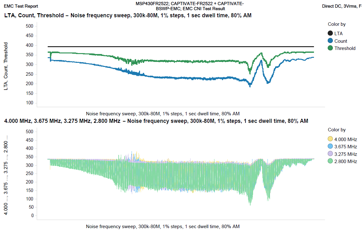
    It's been some time, but I did want to circle back to this thread.  I re-visited the tuning for the CAPTIVATE-BSWP evaluation panel, and I was not able to get an EMC tuning that I was happy with using the current battery-optimized layout as-is.  Using a version of the CAPTIVATE-BSWP board modified for line powered applications, I get the response shown below.  You can see how the filtered count and raw count values are impacted by noise at various noise frequencies, and how the dynamic threshold tracking adapts to this.

    The dense ground shielding used in the modified layout makes the system much more stable.

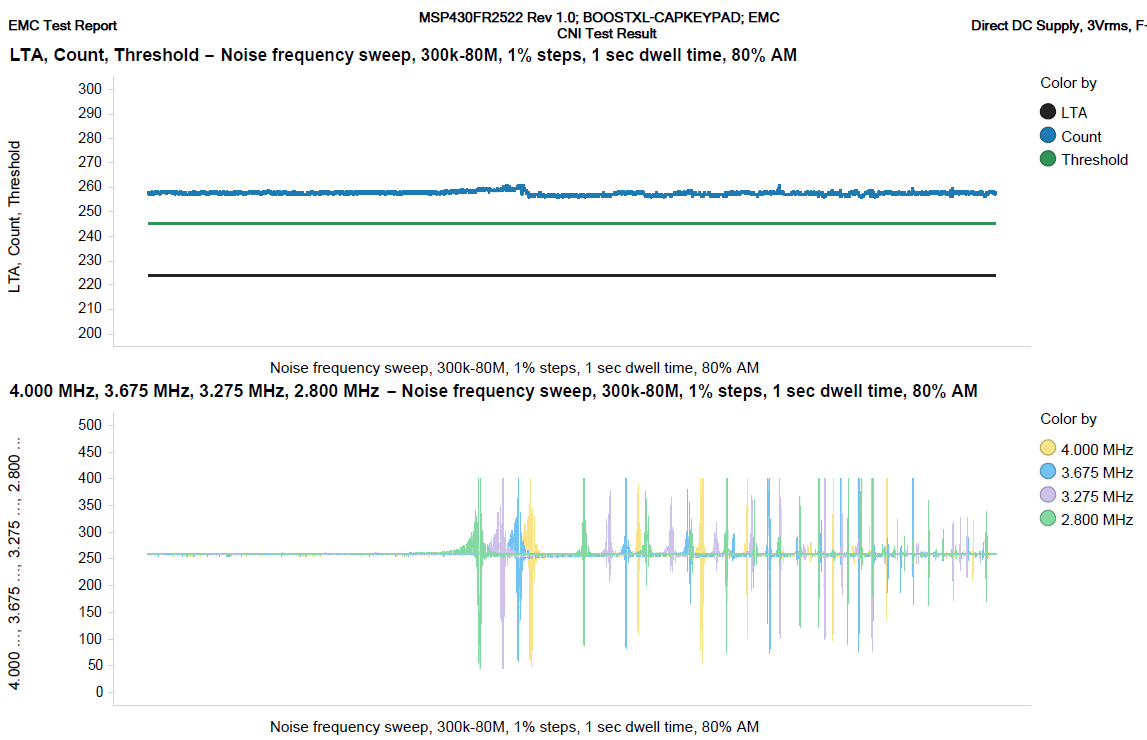
    For the mutual-mode, the behavior is different; there is no sensitivity change while noise is applied; rather, disturbances are dealt with via frequency hopping alone as shown below and no threshold manipulation is needed.  This makes mutual mode sensors easier to get up and running with because there is no threshold manipulation algorithm to tune.

    Mutual-mode sensors do require 68 pF RX-GND capacitors to achieve this performance level.

    Regards,
    Walter

**Attention** This is a public forum