This thread has been locked.

If you have a related question, please click the "Ask a related question" button in the top right corner. The newly created question will be automatically linked to this question.

MSP430G2744: Problem with UART IO at MSP430G2744

Part Number: MSP430G2744

Hello!

We have sensor that controlled by MSP430G2744. It connected to our microcontroller Nordic nRF52832 via UART via next 2 IOs: P3.5/UCA0RXD/UCA0SOMI & P3.4/UCA0TXD/UCA0SIMO.

We see that P3.4/UCA0TXD/UCA0SIMO is constantly damaged during time. If we doing constantly on/off to power of the board this port can get damaged very fast. We asked the question at nordic forum -and they 

think that maybe a Nordic get phantom powered by MSP430G2744 via IO that connected to it. 

We tried to isolate the IOs between nRF and MSP - with buffers and/or series resistors/LPFs, diodes but they only made longer the period that device worked. If before the device worked one day, after different fixes it could hold up with constant power on/off switches about 2 weeks. But at the end it get damaged.

Can you help us to protect the MSP IOs so it will no damaged?

Thank you

  • Hi,

    please let me clarify your issue to help identifying possible solutions:

    1) You connect the MSP430G2744 to nRF52832 via UART pins P3.5 and P3.4

    2) You see that P3.4 is damaged after a short period of time.

    So, when saying you constantly power on/off your board, is this the power supply which switches between on and off?

    Do you see that your UART communication then stops working or what do you mean by MSP IO damaged?

    Shevchenko Maxim said:

    they think that maybe a Nordic get phantom powered by MSP430G2744 via IO that connected to it. 

    Did you verify that the Nordic is drawing current from MSP when there shouldn't be any current flowing?

    Please help me understand your issue a bit better to troubleshoot the issue.

    Thanks and best regards,

    Britta

  • Hello

    1. Yes, you right. I connect MSP430G2744 that placed on purchased sensor to nRF52832 via UART pins P3.5 and P3.4

    2. 

    Britta Ruelander said:
    So, when saying you constantly power on/off your board, is this the power supply which switches between on and off?

    Yes, I switch on/off power supply 5V to the board.

    Britta Ruelander said:
    Do you see that your UART communication then stops working or what do you mean by MSP IO damaged?

    Before I see data running from MSP via its TX pin. Now I see it constantly at 0. When second pin (RX) is at '1' state but it controlled by nRF.

  • Hi,

    thanks for the clarification.
    Are any other parts of your application also affected by the power on/off? I.e. did you verify if the MSP430G2744 powered up properly after the reset and the UART is the only part of your application which is not working anymore? Do you still have access to the MSP430 via JTAG so that you can debug what's happening? If so, can you verify by debugging that a value has been written to TxBuf?

    Please share your findings with me.
    Thanks and best regards,
    Britta
  • Britta Ruelander said:
    Are any other parts of your application also affected by the power on/off? I.e. did you verify if the MSP430G2744 powered up properly after the reset and the UART is the only part of your application which is not working anymore?

    All other parts at our board still working good after a lot of power on/off

    Britta Ruelander said:
    Do you still have access to the MSP430 via JTAG so that you can debug what's happening? If so, can you verify by debugging that a value has been written to TxBuf?

    I don't have access to JTAG because MSP430 is placed at sensor that we use. But by sampling other IOs at MSP430 - it seems it still working

  • Thanks for answering my questions.

    If you're positive that the MSP430 properly powered up and is functioning, then I assume Tx is not transmitting but the rest, as you said, is working just fine.

    Can you somehow check, if all settings are correctly, baud rate, Tx Buffer, clock, interrupt flags and so on?

    Besides, are you able to reproduce this issue on a different unit, showing that Tx is working for a couple of supply on/ off cycles and lateron it stops functioning?

    What's the freqency of power on/off? How long will it be powered on and off respectively? are the power on and off conditions meeting the device specification? Please check the device datasheet for details.

    Best regards,

    Britta

  • Britta Ruelander said:
    Can you somehow check, if all settings are correctly, baud rate, Tx Buffer, clock, interrupt flags and so on?

    Yes it works right.

    Britta Ruelander said:
    Besides, are you able to reproduce this issue on a different unit, showing that Tx is working for a couple of supply on/ off cycles and lateron it stops functioning?

    I tried this at about 10+ our units and it get damaged.

    Britta Ruelander said:
    What's the freqency of power on/off? How long will it be powered on and off respectively? are the power on and off conditions meeting the device specification? Please check the device datasheet for details.

    Yeah, all specifications are fine with data sheet. The frequency of power on/off is 0.0625 Hz - every 8 seconds it change its state.

  • Hi,

    thanks for the feedback!
    Can you confirm that when you see the Tx stopped working it's not coming back after the next reset? It's dead for good?

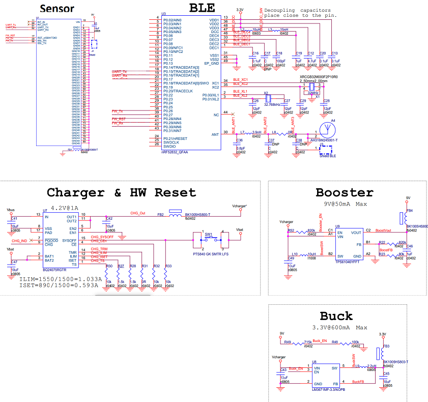
    Besides, would you mind sending me the schmematic of the whole board? I'm especially interested in the external circuitry around the MSP430 and the power supply circuit. Also the Rx/ Tx connection to the nRF device.
    Also, can you check if the UART communication continues to work when talking to a different device than the nRF52832, for example a second MSP430? I'd really like to rule out that it is somehow related to the external connections to start looking MSP430 internal.

    Thanks again and best regards,
    Britta
  • Britta Ruelander said:
    thanks for the feedback!
    Can you confirm that when you see the Tx stopped working it's not coming back after the next reset? It's dead for good?

    Yes, it is no back to work.

    Britta Ruelander said:
    Besides, would you mind sending me the schmematic of the whole board? I'm especially interested in the external circuitry around the MSP430 and the power supply circuit. Also the Rx/ Tx connection to the nRF device.
    Also, can you check if the UART communication continues to work when talking to a different device than the nRF52832, for example a second MSP430? I'd really like to rule out that it is somehow related to the external connections to start looking MSP430 internal.

    It happen also at evaluation module of sensor where to MSP430 connected CMWC1ZZAAF Wi-Fi module with some TI controller inside.

    The relative schematic are:

    Here MSP430 is placed inside the sensor. And we don't have the schematic of the sensor..

  • Thanks for sending the schematic.
    I have a couple of more questions to troubleshoot what's leading to your problem:
    1. When powering off, are you simply taking away the power supply or are you actively pulling the voltage to GND? in case you're taking away the power supply, can you verify that the MSP is properly powered down and not floating on a medium voltage level due to slow discharge of capacitors? in that case you might want to try to actively pull the supply voltage to zero and see if you can still reproduce the problem.
    Maybe you could also post Vcc oscilloscope plots so that I can have a look at the ramp curves (up and down) at the MSP430. Do you see any voltage spikes?
    2. Can you ensure that the voltage at the affected pin is not exceeding the absolute maximum ratings and meets the recommended operating conditions? Note that stress at the pins may cause permanent damage to the device/ the pins. Maybe you could also post oscilloscope plots of the voltage at the affected pin.

    Hopefully you can provide the details and we finally pin the problem down.
    Thanks and best regards,
    Britta
  • Britta Ruelander said:
    1. When powering off, are you simply taking away the power supply or are you actively pulling the voltage to GND? in case you're taking away the power supply, can you verify that the MSP is properly powered down and not floating on a medium voltage level due to slow discharge of capacitors? in that case you might want to try to actively pull the supply voltage to zero and see if you can still reproduce the problem.
    Maybe you could also post Vcc oscilloscope plots so that I can have a look at the ramp curves (up and down) at the MSP430. Do you see any voltage spikes?

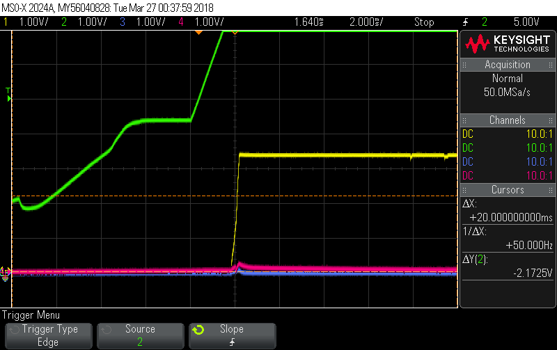
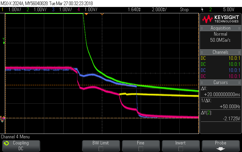
    I am taking away the power supply. So the power is still at board capacitors for some time. Here the screenshots.

    Here it is a power-up:

    Here Green is 9V of the sensor, Yellow is 3.3V for nRF at a board, blue is TX UART  the signal of MSP that destroyed, pink is RX UART.

    Here the power-down:

    Here the power-up of 9V on-board, 3.3V on-board for nRF and 3.3V on-sensor for MSP:

    Yellow - 9V on-board, Green - 3.3V on-board for nRF and Blue - 3.3V on-sensor for MSP.

    Britta Ruelander said:
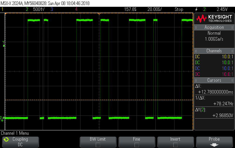
    2. Can you ensure that the voltage at the affected pin is not exceeding the absolute maximum ratings and meets the recommended operating conditions? Note that stress at the pins may cause permanent damage to the device/ the pins. Maybe you could also post oscilloscope plots of the voltage at the affected pin.

    All those are seems ok.

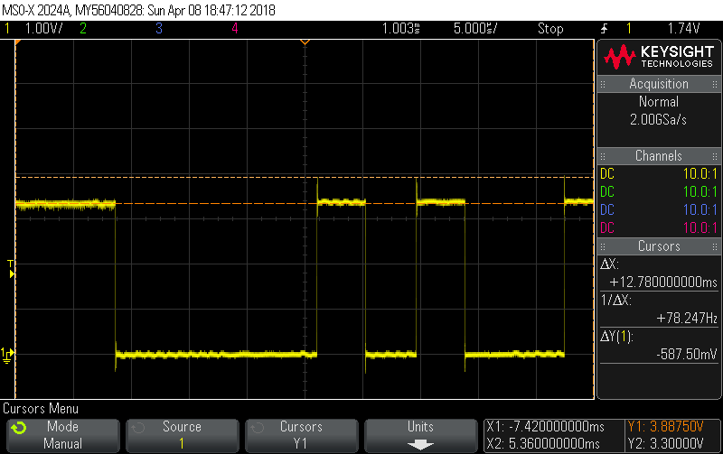
    Here the MSP-430 RX signal during communication:

    Here the MSP-430 TX signal during communication:

    Here we see some over-under shoot but it created at MSP430 itself..

  • Hi,

    those screenshots look good from our perspective.
    We'll need to take this to our Quality group for them to make a thorough check of you issue. Therefor we'll need to take is offline via personal mail.
    I'll get in contact with you and talk you through the next steps.

    Best regards,
    Britta
  • Is it true, that the blue signal at the third graf is the Sensor signal to the MSP430?

    This Signal has 3 Volt before the VCC of the MSP. This could disturbe the reset or power up of the MSP430.

    Is this right?

  • Hello

    The blue signal at 3rd graph is on-sensor 3.3V supply for MSP430, no signal
  • Hi,

    thanks for the clarification.
    I believe the contact with our quality team has been established.
    I'll go ahead and close this thread to avoid communication on two parallel channels.

    Best regards,
    Britta

**Attention** This is a public forum