This thread has been locked.

If you have a related question, please click the "Ask a related question" button in the top right corner. The newly created question will be automatically linked to this question.

MSP430F6734A: Wakeup from LPM3 when Auxiliary Supply Switch

Part Number: MSP430F6734A
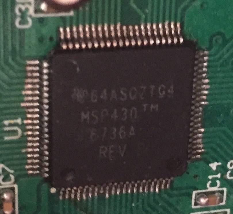
Other Parts Discussed in Thread: MSP430F6779

Hi,

We have a metering application that use one battery and one main power.

VCC = 3.3V comes from AC power.

AUX1VCC = 3.6V battery

AUX2VCC = 0V grounded

AUX3VCC = VDSYS so there will be always power either from VCC or AUX1.

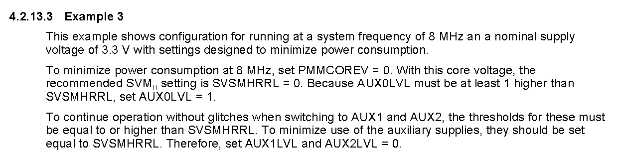
MSP works at 8Mhz with VCore=0 that is 1.35V

My intention is that MSP should enter to LPM3 if we are getting power from battery (AUX1) and wake up if power switches back to AUX0 (that is VCC)

AUX module is configured for fully hardware controlled. There is no software interaction while AUX module does its job.

My configuration below works as expected but sometimes (I hate that word) It doesn't switch to VCC automatically even main power restored.

----

So I studied AUX Module, PMM module and SVS module again in the user manual.

But I didn't understand how exactly they interact each other.

Q1: Do I need to enable SVM (Supply Voltage Monitor) High side in order AUX module to work properly? If yes why and what behavior of AUX module changes if I disable it?

Q2: Will AUX module continue operate in LPM3 mode? Can AUX switch interrupt wake the MCU officially? No one mention this.

Q3: PMM module seems to have a lot of errata. PMM11, PMM15 and PMM26

#pragma vector =  AUX_VECTOR	/* 0xFFE6 AUX Supply */
__interrupt void AUX_ISR(void)
{
	AUXIFG = 0;
	LPM3_EXIT;
}

void main(void)
{
	// SVS -> Supervisor results in a power - on reset(POR) event
	// SVM -> Monitoring results in the generation of an interrupt flag that software may then handle, required by AUX module!!
	//
	// Low side monitors Vcore
	// Highside monitors VCC
	SFRIE1 = 0u;
	SFRRPCR = SYSNMI | SYSRSTRE | SYSRSTUP; // disable reset pin, ERRATA PMM26: Device lock-up if RST pin pulled low during write to SVSMHCTL or SVSMLCTL
	PMMCTL0_H = PMMPW_H;
	PMMCTL0_L = PMMCOREV_0; // PMM Core Voltage 0 (1.35V)

	SVSMIO = 0u;
	PMMIFG = 0u;
	PMMRIE = 0u; // ERRATA PMM7: PMMRIE default conditions different than user guide

	SVSMHCTL = SVSHE | SVSHRVL_1 | SVSMHACE | SVSMHRRL_1 | SVSHFP | SVMHE | SVMHFP; // that settings for VCC, Warning SVSHFP and SVMHFP bit is added due to PMM15 errata!!
	while((PMMIFG & SVSMHDLYIFG) == 0u);

	PMMIFG = 0u;
	SVSMLCTL = SVSLE | SVSLRVL_0 | SVSMLACE | SVSMLRRL_0; // that settings for Vcore and used in slow performance mode
	while((PMMIFG & SVSMLDLYIFG) == 0u);

	PMMIFG = 0u;
	PMMCTL0_H = 0u; // Lock PMM registers for write access
	SFRRPCR &= ~SYSNMI; // enable reset pin

	//test = PMM15Check(); this returns 0 as indicated in errata, so we are not affected from PMM15

	// Enable control of DVCC, AUXVCC1 but not for AUXVCC2
	AUXCTL0 = AUXKEY;

	// AUXLVLx = 0 -> 1.67V - 1.74V - 1.80V
	// AUXLVLx = 1 -> 1.87V - 1.95V - 2.01V
	// AUXLVLx = 7 -> 2.91V - 3.02V - 3.10V
	AUXCTL2 = AUXMR_0 | AUX0LVL_7 | AUX1LVL_1 | AUX2LVL_0;
	AUXCTL1 = AUX2MD; // AUXVCC2 is software controlled and disabled
	AUX2CHCTL = AUXCHKEY;
	AUX3CHCTL = AUXCHKEY;
	AUXADCCTL = 0u;
	AUXIFG = 0u;
	AUXIE = 0u;
	AUXCTL0_H = 0; // disable
	..
	..
	SET MCLK to 8Mhz
	..
	..	
	
	while(true)
	{
		// if we are not powered from VCC then enter to LPM3
		AUXIFG = 0;
		if((AUXCTL1 & AUX0OK) == 0)
		{
			// wake up when main power back
			AUXIE = AUXSWGIE | AUX0SWIE;


			// ERRATA PMM11: MCLK comes up fast on exit from LPM3 and LPM4
			UCSCTL5 |= DIVM0_L; // MCLK/2=4Mhz
		
			// enter to LPM3
			__RESET_WATCHDOG();
			__bis_SR_register(LPM3_bits + GIE);
		}
		
		// ERRATA PMM11: MCLK comes up fast on exit from LPM3 and LPM4
		__delay_cycles(100);
		UCSCTL5 &= ~DIVM0_L; // restore MCLK to 8Mhz again

		AUXIE = 0;	
	}
	
}

  • Hello BasePointer,

    To answer your questions:

    Q1: For hardware-controlled mode the SVM in the PMM must be enabled and configured as discussed in section 4.2.4 in the datasheet. There are also additional considerations outlined in section 4.2.5 for what levels in both modules to choose. If SVM is disabled, then hardware controlled switching is not available.

    Q2: The AUX module should work through the different LPMs as it is not clocked through MCLK/SMCLK/ACLK, but straight from VLO. The AUX ISRs should wake up the device through LPMs with the exception of the LPMx.5 modes as they only have specific interrupts to wake up from those modes.

    Q3: Yes, there are several PMM errata that you may need to be aware of or work around.

    Also, have you seen the following TIDesighn? It goes through several AUX switching scenarios and configurations that maybe useful to your issue.

    www.ti.com/.../TIDM-AUX-MODULE
  • The MCU works at 8 Mhz in Active mode and our product consumes around 2mA in this mode.
    When VCC doesn't exist it consumes 3.5uA in LPM3 mode from the battery that is connected to AUX1.
    That is expected behavior of our product.

    But "sometimes" MSP430 in LPM3 mode enters into an unknown state when main VCC is restored. It should wake up and enter into active state by switching from AUX1 to VCC, but that is not happening.
    While in LPM3 and powered from battery, if VCC is restored, MCU doesn't wake up, instead it enters into a strange state.

    That state I can describe as that MCU starts consuming 2mA from battery while VCC exists and no code execution as if it was still in LPM3, and also watchdog timer doesn't reset the MCU. (Watchdog always active and sourced by VLO)

    If I turn off the VCC back in this unknown state while AUX1 battery is available, and turn on VCC back, MCU enters into a known state back and continue working as expected.

    PS1: We measured the rise time of VCC and it is 475V/sec. Max spec is 1000V/sec in the datasheet.

    PS2: We tested with also recommended settings given in example 3 in the user guide. result didn't change. Phenomena still exists randomly. 

    ..
    SVSMHCTL = SVSHE | SVSHRVL_0 | SVSMHACE | SVSMHRRL_0 | SVSHFP | SVMHE | SVMHFP; // that settings for VCC, Warning SVSHFP and SVMHFP bit is added due to PMM15 errata!!
    while((PMMIFG & SVSMHDLYIFG) == 0u);
    ..
    // Enable control of DVCC, AUXVCC1
    AUXCTL0 = AUXKEY;
    
    // AUXLVLx = 0 -> 1.67V - 1.74V - 1.80V
    // AUXLVLx = 1 -> 1.87V - 1.95V - 2.01V
    AUXCTL2 = AUXMR_0 | AUX0LVL_1 | AUX1LVL_0 | AUX2LVL_0;
    ..

  • Hello BasePointer,

    Can you post a picture of the markings on your device?
  • There is conformal coating on it, it is a little bit hard to read.

    64ASCZTG4

    MSP430

    F6736A

    REV B

  • To simplify the problem, today I disabled wake up mechanism completely by clearing GIE flag just before entering into LPM3.
    So instead of "__bis_SR_register(LPM3_bits + GIE);" command, I just used "__bis_SR_register(LPM3_bits);" to enter into LPM3. And only source to exit from LPM3 is reset.

    And I start observing behavior of Auxilary Power Supply Module in LPM3.

    As I indicated before in our product VCC = 3.3V comes from AC power, AUX1VCC = 3.6V battery, AUX2VCC = 0V grounded, AUX3VCC = VDSYS.
    During the test, I measure current as well consumed from AUX1 that is battery.

    I started testing, just by turning on and off VCC periodically (every 4-5 seconds).
    Normal case, when VCC exists, we consume 0.5uA from the battery and 3.7uA when VCC is missing.

    After couple of turn off/on cycles, while VCC 3.3V exists, MSP started consuming very high current from the battery that is connected only to AUX1 pin (remember MSP is still in LPM3) And from that point, when I turn off VCC, MSP get reset and enter into LPM3 immediately again by our code.

    Here is the minimal code that shows the problem:

    void main(void)
    {
    	__disable_interrupt();
    	WDTCTL = (WDTPW | WDTHOLD_L);
    
    	// Enable control of DVCC, AUXVCC1 but not for AUXVCC2
    	AUXCTL0 = AUXKEY;
    
    	// AUXLVLx = 0 -> 1.67V - 1.74V - 1.80V
    	// AUXLVLx = 1 -> 1.87V - 1.95V - 2.01V
    	// AUXLVLx = 2 -> 2.06V - 2.14V - 2.21V
    	// AUXLVLx = 3 -> 2.19V - 2.27V - 2.33V
    	// AUXLVLx = 6 -> 2.91V - 3.02V - 3.10V
    	AUXCTL2 = AUXMR_0 | AUX0LVL_6 | AUX1LVL_3 | AUX2LVL_3;
    	AUXCTL1 = AUX2MD; // AUXVCC2 is software controlled and disabled
    	AUX2CHCTL = AUXCHKEY;
    	AUX3CHCTL = AUXCHKEY;
    	AUXADCCTL = 0u;
    	AUXIFG = 0u;
    	AUXIE = 0u;
    	AUXCTL0_H = 0; // disable
    
    	while(true)
    	{
    		// dont wake up until mcu reset
    		__bis_SR_register(LPM3_bits);
    	}
    }

  • Hello BasePointer,

    Can you look into implementing the AUXPMM2 errata workaround for scenario 2? Your situation may not exactly fit, but I want to make sure its ruled out completely.

    Also, can you repeat your tests with the MSP430F6779_AUX)04.c (aka Example 4) from the link above? This is the closest configuration to what you have.

    Can you also share a snippet of your schematic showing the MSP430 and its power connections?
  • Hi Jace,

    I will check  MSP430F6779_AUX_04.c in detail and update the thread.

    About AUXPMM2 errata:

    >> Scenario 1: When the AUXPMM is configured for hardware- or software-controlled
    >> switching and the module switches from DVCC to AUXVCC2, latch-up current can...

    Here we don't use AUXVCC2.

    >> Scenario 2: When a battery is connected to DVCC, AUXVCC1 or AUXVCC2 as the first
    >> voltage supply, due to the low internal resistance of the battery a very fast rise...

    Here we have 3.6V battery connected to AUXVCC1 but with series 10ohm resistor (R61 in the schematic).

    We have increased the series resistor value first to 33ohm then 100ohm. It didn't help for our problem. Issue still exists.

    But when problem occurred, it reduced the current consumed from the battery while DVCC exists.

    So our conclusion is that AUXPMM2 errata is not the one that affects us.

    Here is the schematic that shows all power domains:

  • Hello,

    To clarify your schematic, B3V3 is being sourced by VDSYS correct?

    Any particular reason for C19, C29, C30? The GPIO power shouldn't need the extra capacitance. I'm worried the extra capacitance here is leading to a power ramp issue for the MSP430. One test would be to remove these as well.

    Any luck with the Example 4 test?
  • Yes B3V3 is sourced by VDSYS.

    We removed C19 and C29 that were placed to improve EMC performance of the product.

    We also changed C61 value from 100nF to 4.7uF as suggested in the datasheet.

    It seems that problem occurrence rate is decreased.

    But unfortunately we observed the problematic case one time with even updated values.

    We will continue testing and let you know more. Especially with Example 4.

    Now we are trying to automate the test system so that we can convince ourself faster.

**Attention** This is a public forum