This thread has been locked.

If you have a related question, please click the "Ask a related question" button in the top right corner. The newly created question will be automatically linked to this question.

MSP432P401R: Error connecting to the target: (Error -261 @ 0x0)

Part Number: MSP432P401R

IDE: CCS

Hello There,

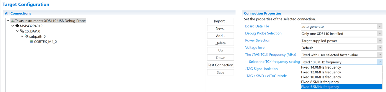
Whenever I try to debug my custom MSP432 board having RGC(64 pin package), I get following error-

Error connecting to the target: (Error -261 @ 0x0)
Invalid response was received from the XDS110. (Emulation package 8.4.0.00006)

Also, I'm using Device in LDO mode. Debugging the device with SWD (TCK and TMS) using Launchpad's debugger.

Regards,

Keshav Aggarwal

  • I think that's an issue with LDO mode. As The launchpad uses DCDC and my custom board is using LDO.

    How I can switch from DCDC to LDO in syscfg. What configuration changes are needed?

    Regards,

    Keshav Aggarwal

  • Hello,

    Keshav Aggarwal said:
    How I can switch from DCDC to LDO in syscfg. What configuration changes are needed?

    First, open your .syscfg file and go to "Power", then select "4" for "Custom Performance Levels". Then, change "Active State" to "LDO".

    Regards,

    James

  • Hello James,

    Thanks for your reply. I have added a custom performance level and changed the Active state to LDO, still it's showing the same error.

    Regards,

    Keshav Aggarwal

  • Hello,

    To rule out if this is a syscfg issue or not, what happens when you try to program a simple blink LED code example on the custom board? You can find the code examples in Resource Explorer in CCS. I suspect this is a connection or hardware issue. Since you have a LaunchPad, does it work? If that works, then I would strongly suspect a hardware issue.

    Regards,

    James

  • Hello James,

    It is working perfectly on Launchpad. I have tested it on our 3 custom boards.

    We have also verified the designs still no success.

    Please find the attached custom board connections we are using and my syscfg file.

    empty.rar

  • The log while Testing connection in Target Configurations of the project shows the SWD connection is good.

    [Start: Texas Instruments XDS110 USB Debug Probe]
    Execute the command:
    %ccs_base%/common/uscif/dbgjtag -f %boarddatafile% -rv -o -S integrity
    [Result]

    -----[Print the board config pathname(s)]------------------------------------
    C:\Users\Keshav\AppData\Local\TEXASI~1\CCS\
        ccs930\0\0\BrdDat\testBoard.dat
    -----[Print the reset-command software log-file]-----------------------------
    This utility has selected a 100- or 510-class product.
    This utility will load the adapter 'jioxds110.dll'.
    The library build date was 'Nov 25 2019'.
    The library build time was '16:55:29'.
    The library package version is '8.4.0.00006'.
    The library component version is '35.35.0.0'.
    The controller does not use a programmable FPGA.
    The controller has a version number of '5' (0x00000005).
    The controller has an insertion length of '0' (0x00000000).
    This utility will attempt to reset the controller to enter SWD mode.
    -----[Print the reset-command hardware log-file]-----------------------------
    This emulator does not create a reset log-file.
    -----[Perform the SWD Mode Integrity test]-----------------------------------
    This test will read the IDCODE register 1 time.
    The IDCODE register value is 0x2ba01477.
    The SWD Mode Integrity test has succeeded.
    [End: Texas Instruments XDS110 USB Debug Probe]
  • Part Number: MSP432P401R

    Hello All,

    I need urgent help for my issue with custom MSP432 (64-pin) board.

    https://e2e.ti.com/support/microcontrollers/msp430/f/166/t/918268

    Any help would be appreciated.

    Thanks,

    Keshav Aggarwal

  • Hi Keshav,

    I am also facing the same issue, I tried debugging the custom board (having LDO mode operation connection without an inductor at VSW) with software selection at DC-DC operation mode mistakenly, Since then i am getting the same error.

    Is this could be the possible issue, and how can i resolve it? Is there any other way to get the a little quicker resolution?

    Please Suggest Correct LDO config setting.

  • Hello ,

    I've merged your duplicate posts and also see you've made another similar post here. In the future, please do not make duplicate threads about the same issue.

    I did some searching on the forum for this (Error -261 @ 0x0), and I found several posts that should help you resolve the issue. There can be several possible causes ranging from EnergyTrace, USB hubs, USB 2.0/3.0 compatibility, USB cables, etc.

    CCS/LAUNCHXL-CC26X2R1: IcePick_C: Error: (Error -261 @ 0xFFFFFEFB) Invalid response was received from the XDS110 (Emulation package 8.0.27.9)

    CCS/MSP432P401R: Error -261 @ 0x0 Invalid response was received from the XDS110 (JTAG comm error)

    CCS/TMS320DM8148: JTAG : IcePick_D_0: Error: (Error -261 @ 0xFFFFFEFB) Invalid response was received from the XDS110

    CCS / AWR1843 : Invalid response was received from the XDS110. (Emulation package 8.4.0.00006)

    Perhaps, you're using a different USB port than the LaunchPad to program your custom boards or you're using a USB hub. I would also recommend disconnecting all other targets from the PC and just connecting one at a time. If you're using different PCs, I would recommend using the one used with the LaunchPad.

    Regards,

    James

  • Hello James,

    Thanks for replying. I have already tried all the suggestions but no success.

    Although I can regenerate this error in launchpad as per vidushi's comment here

    So, Now it seems that the issue is related to incorrect LDO configuration. Please visit the above post to see how she regenerated the issue.

    Awaiting your reply.

    Regards,

    Keshav Aggarwal

  • Hello,

    Please go through the Custom Power Performance Level section in the SimpleLink Academy. In Task 2, an example is given on how to configure .syscfg to use the LDO. Please follow those instructions carefully.

    You mentioned earlier that you aren't able to debug your custom boards. I'm assuming that means you can't program them at all, not just unable to debug. If that's the case, then an incorrect .syscfg is not the issue. The device by default uses the LDO to power up, so I suspect there is a hardware issue such as a wrong or missing connection that is ultimately causing the issue. Have you followed the recommendations for each pin in the datasheet?

    Regards,

    James

  • Hello we are already following recommendations mentioned in Datasheet.

    Although I have shared my circuit schematic via a private message. Please accept my invitation.

    Awaiting your reply.

    Regards,

    Keshav Aggarwal

  • Hi Keshav,

    Thanks for sharing your schematic. I've looked over it and had a few comments.

    1. I don't see the recommended pull-up resistor (47 kOhm) or the pull-down capacitor (1 nF) connected to the !RST pin. I see that the SWD connections are fed through J4 (CON8), so that could add a lot of capacitance to these sensitive, fast signals. These connections should be as short as possible.

      Also, you may want to slow down the TCK frequency. To change these settings, select your .ccxml target configuration and make sure the connection is set to Texas Instruments XDS110 USB Debug Probe. Then in "Advanced Setup", click "Target Configuration", select "Texas Instruments XDS110 USB Debug Probe" and then under "Connection Properties" select a slower frequency for the TCK frequency setting (e.g. 5.5MHz default frequency). Be sure to click "Save" before continuing.

    2. Have you confirmed that the device is getting powered up by confirming 3.3 V on DVCC and AVCC? I see that power and ground is also fed through J4 (CON8), so check those connections too.

    3. The EPAD (Pin 0) seems to represent the thermal pad, but it isn't connected to DVSS as recommended by Footnote C in Figure 4-3 in the datasheet. Did you make this connection manually in your layout?

    Regards,

    James

**Attention** This is a public forum