This thread has been locked.

If you have a related question, please click the "Ask a related question" button in the top right corner. The newly created question will be automatically linked to this question.

Custom board with TM4C not working. Error connecting to target

Other Parts Discussed in Thread: TM4C1230H6PM

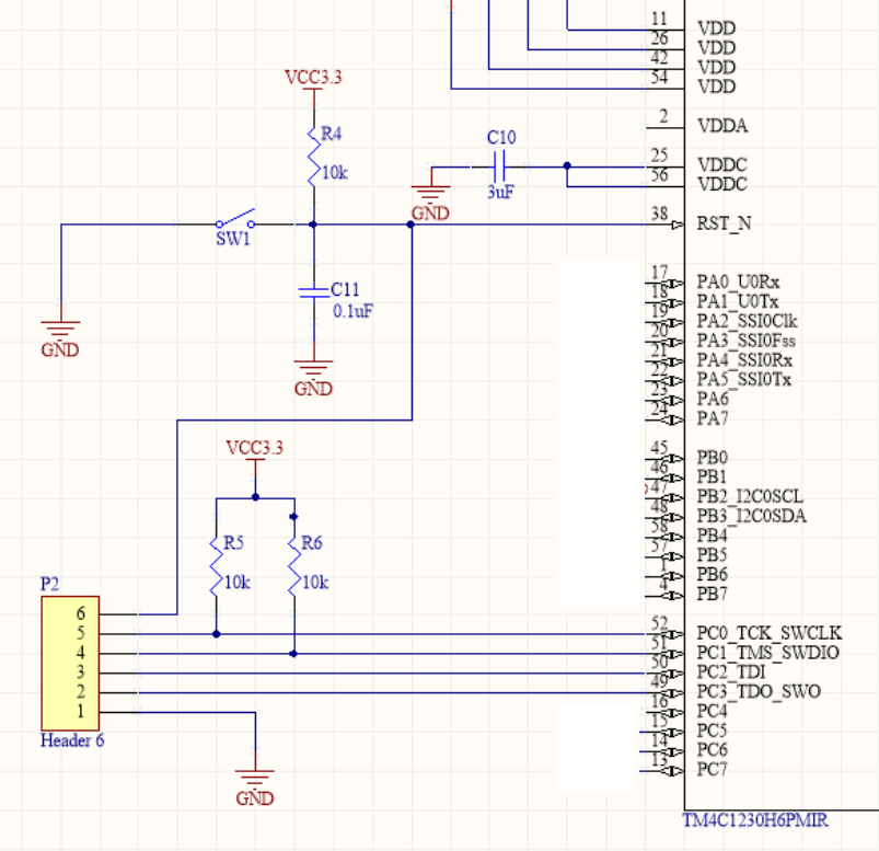
I have made a custom board using TM4C1230H6PM. I am using JTAG to load & debug the program into the board. The connections are made as shown in the picture below.

I am using the ICDI on TM4C123GXL launchpad load program into the board.

I tried using CCS v6, and it gives me error which says "Error connecting to target"

I tried using LMFlash programmer, and it gives me error "Error connecting to target - 0"

I have tried literally everything that this forum posts suggests, referred all documents relating to JTAG, but still no luck.

I have checked the pin to pin connections for all 4 JTAG signals - TCK, TMS, TDI and TDO. They are correct. 

Somewhere in this forum, it was mentioned that the voltage on RESET pin after connection is made should be 3.3V, but here I am getting 2.7V. I tried using a different launchpad, and a different custom board, but still voltage is 2.7V.

How to diagnose this problem? What could have possibly gone wrong in this schematic?

  • Hello Shashank,

    Please refer to the following application note for the first level of debug.

    www.ti.com/.../spma075.pdf

    Regards
    Amit
  • Hello Amit,

    I referred to document you linked. And did the following.

    1. Tried to unlock the MCU using LM Flash tool. Everything seemed to go fine, I did not get any errors. But after this when I tried loading program into the MCU, still same error as earlier.

    2. As I do not have a XDS probe, I could not test connection with CCS 6. Is there some other way to do this?

    I also tried the following.

    I have two TM4C123GXL launchpads. I connected one of them as ICDI, and other one as a separate board, and tried to load program into the second one with the first one(as ICDI). This worked. The program gets loaded.

    After this I thought that there might be some problem with my custom board, so I tried in a different custom board. Still I got the same error.

    1. Is the schematic that I posted with the question correct? - Reference for this was the schematic of TM4C123GXL. As far as I see it, both are exactly the same.

    2. After making connections, the voltage on the nRESET pin on the custom board reads 2.7V. I am not able to figure out why this is happening as all connections are correct. The document you linked mentions that it should be 3.3V. Is 2.7V ok here?
  • Hello Shashank

    The first line of the debug steps are

    Check with a digital multi-meter that the VDD and VDDA supply rails are 3.3 V.
    (a) If not, then check the power supply aspect of the design.

    I believe if you check that against your schematic you would have realized the mistake made.....

    Regards
    Amit
  • Hi Amit sir,
    I am using TM4C1294 Launchpad for mimicking bird. I have done successfully but during execution I connected I/O pins to the board using copper wire. Now that I don't want to include whole board into the project. How can I do that? As I am novice to embedded system. I want to make new PCB board with TM4C controller, how can I load the program? Can I use above method as my fellow member Shashank stated?
    Sorry to extend this thread I thought it is good to ask question as it is for load and debug.
    Please help me.
    Thanks,
    Mayur
  • Hello Mayur,

    Did you read the application note I posted earlier?

    Regards
    Amit
  • Hi,

    Please note some USB connection ports have 100 mA capability, while others have more, 500 mA. As there is an slew rate minimum imposed on startup conditions, a more capable port will behave better than a smaller one. Depends also on peripherals/circuits added by you, which also consume power at startup.

  • Hello Petrei,

    The use has still not analyzed his schematic with respect to the Application Note debug steps for JTAG not working..... It is is pretty evident why it may not be working.

    Regards
    Amit
  • Amit Ashara said:
    I believe if you check that against your schematic you would have realized the mistake made.....

    Yes Amit. I realized the mistake.

    I assumed that VDDA is required for just ADC to operate. And as I was not using ADC module in the schematic, I kept it connected.

    Once I connected VDDA to 3.3V, the problem was solved.

    Thanks a lot.

  • Hello Shashank

    Thanks for taking a step back to move forward. I appreciate it a lot. The application note was specifically written for a lot of forum users who in the past may have run into the same set of issues and tries to consolidate the information....

    Regards
    Amit