This thread has been locked.
If you have a related question, please click the "Ask a related question" button in the top right corner. The newly created question will be automatically linked to this question.
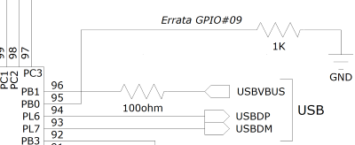
I'm trying to get USB working in device mode with VBUS connected but not ID. I'm using a USB B connector so there is no ID pin. PB0 (USB0ID) is configured as a GPIO input and tied to ground via a 1k resistor per errata GPIO#09. PB1 (USB0VBUS) is connected to the USB connector via a 100 ohm resistor as recommended in the system design guidelines.
When I have the usblib stack configured in eUSBModeDevice mode, my PC is unable to see my device. If I use eUSBModeForceDevice instead, everything works except connect/disconnect notifications. As far as I can tell, the only difference between these two modes is the value written to USBGPCS.DEVMOD. In regular device mode the stack writes 0, which makes the controller use external VBUS and ID signals, and in forced device mode it writes 3, which makes the controller internally force signals both high. Based on that, the behavior I observed is expected.
Although usblib does not expose it, the datasheet has a value for USBGPCS.DEVMOD that is supposed to make the controller use the external VBUS signal, but force ID high internally. I've tried activating this by calling the driverlib function USBModeConfig with USB_MODE_DEV_VBUS (5) after the library initializes the controller, but it doesn't help. I've tried a number of things and almost completely ruled out the possibility that the timing of my DEVMOD change has anything to do with the problem. Am I misreading what DEVMOD=5 does? The driverlib documentation seems to be consistent with my understanding: "USB_MODE_DEVICE_VBUS enables operating only as a device with monitoring of VBUS pin. This configuration enables disconnect detection while still forcing device mode."
Here's a simplified version of my code:
EnablePeripheral(SYSCTL_PERIPH_USB0); EnablePeripheral(SYSCTL_PERIPH_GPIOB); EnablePeripheral(SYSCTL_PERIPH_GPIOL); GPIOPinTypeGPIOInput(GPIO_PORTB_BASE, GPIO_PIN_0); // ID GPIOPinTypeUSBAnalog(GPIO_PORTB_BASE, GPIO_PIN_1); // VBUS GPIOPinTypeUSBAnalog(GPIO_PORTL_BASE, GPIO_PIN_6 | GPIO_PIN_7); // DP, DM USBStackModeSet(0, eUSBModeDevice, NULL); USBDCDFeatureSet(0, USBLIB_FEATURE_USBPLL, &pllFrequency); // *pllFrequency == 240000000 USBDCDCInit(0, &USB_Cdc_Device); // I do check the return value and it's not NULL USBModeConfig(USB0_BASE, USB_MODE_DEV_VBUS);
It appears that DEVMOD=5 is not correctly forcing ID and the external signal is still being used. If I reconfigure PB0 as USB analog instead of GPIO input, it works when the resistor to ground is removed.
Any ideas?
PS: The datasheet has the wrong reset value for the DEVMOD field. It's actually 3 as shown in the reset value for the entire register.
I can actually get ID to be internally forced with eUSBModeForceDevice, which sets DEVMOD=3 (force both high). I just can't do so without also forcing VBUS. My workaround is to configure PB0 as USB0ID, which is that pin's analog/special function. Of course that only works if you didn't use PB0 for something else. Fortunately for me it's one of the few unused pins in my design. I was initially concerned that floating PB0 may trigger GPIO#09, but I guess that's exactly what happens when it's connected to the ID pin of an AB connector and a B cable or no cable is plugged in.
I tried checking the reset value of DEVMOD from a cold start and I'm still getting 3 right after I enable the clock with SysCtlPeripheralEnable(SYSCTL_PERIPH_USB0). In any event the field and register reset values are clearly inconsistent in my copy of the datasheet which is dated June 2014.
Hi,
Thanks for the confirmation. Looks like it is not able to enumerate when you connect the resistor. I wonder if your 100ohm resistor is connected in series between the B connector and the USB0ID pin or connected to ground. If connected to ground the OTG will think it is a host. The ID pin is supposed to be floating if micro-B connector is plugged. If 100ohm is connected in series then I would have imaged the ID pin to still float and the internally pullup activated.
Below excerpt from system design guideline.
If a micro-B cable end is plugged into the USB connector, the ID pin is left floating. In this case, the TM4C129x device's internal pull-up on the USB0ID signal causes the controller to operate in device mode. In order to limit damage from ESD events, a 100Ω resistor should be placed in series between the ID pin on the USB connector and USB0ID(PB0) on the microcontroller.
HI BB,
I tested the same pin functions last night having an similar issues with suspected internal triggered Suspend events. Anyway I discovered the USB package pins (VBUS/ID) remain functional in either mode, Force or Device.
Even after the analog GPIO pins PB0/PB1 were disabled, (USB_O_GPCS) register had no effect to control internal pin states, to my surprise package pins remained active. Only after removing both VBUS/ID 100 ohm series resistors did (USBModeForceDevice) have any effect to control internal states via USB_O_GPCS and library stack functions. The datasheet makes it seem as if the USB0 direct connect package pins can be disabled but it seems in device mode that is not entirely true. That also is relative to call being made to ->
USBDCDFeatureSet(0, USBLIB_FEATURE_POWER, &ui32FeatureSelfPWR);
I'm starting to believe pin state issue has more to do with the internal 1.5k pull up resistor D+ (device mode) over rides USB_O_GPCS register settings if VBUS/ID pins are connected to host. The only time I ever saw it work correctly is when VBUS pin PB0 becomes shorted. Too seems the USB device control descriptor may cause an undesired internal artifact relative to default VBUS Suspend current monitor setting, 500ma/2.