This thread has been locked.

If you have a related question, please click the "Ask a related question" button in the top right corner. The newly created question will be automatically linked to this question.

DRV8432: DRV8432 drive 4xTEC---XLT2418

Part Number: DRV8432

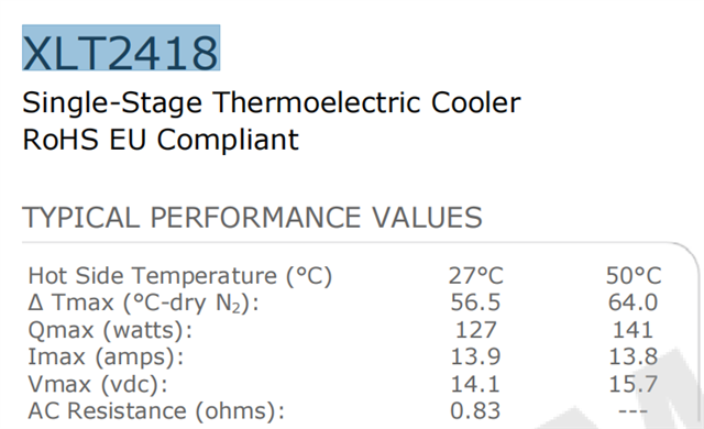
as title,I found TEC driver DRV8432 on your website, which can be used to drive TEC directly, now we need 4 TEC---XLT2418, they are working indepently, 

now we have some questions to confirm,

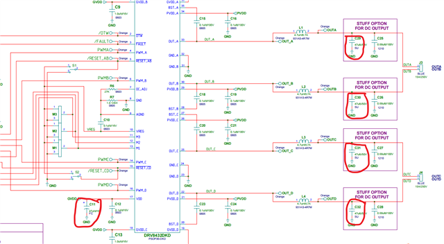
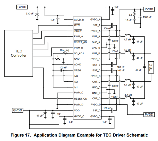
1.the reference design,in 8.2.4 of datasheet,PWM_A and PWM_B are saparately connected, PWM_C and PWM_D are connected together to GND,

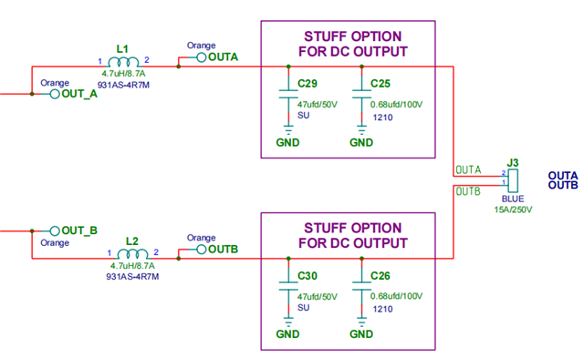
but OUT_A and OUT_B are connected together to TEC one side, OUT_C and OUT_D are connected together to TEC the other side.

why PWM_A and PWM_B separate? can't connect them together to MCU like PWM_C and PWM_D?

 as we know, about DRV8432


a. Heating: OUTA/B voltage is higher than OUTC/D voltage.

b. Cooling: OUTC/D voltage is higher than OUTA/B voltage

so the reference design is just for cooling down, right?

2. if we want to cool down and heat the TEC, how to connect PWM_A,PWM_B,PWM_C,PWM_D?

3. can DRV8432  be used to drive TEC---XLT2418?

4.if we wanted to drive 4xTEC---XLT2418, do we need 4 DRV8432?

  • Hello!

    One of our team members will respond in 24 hours.

    Regards,

    Ryan

  • Hello Dengshan,

    I will be happy to assist you today! I will address your questions in a similar format as they were given: 

    1.) The reference design that you mentioned is set up in a specific Functional mode: Parallel Full Bridge Mode (PFB).

    From section 7.4 on page 15 of the datasheet:

    In In parallel full bridge mode (mode 3), PWM_A controls both half bridges A and B, and PWM_B controls both half bridges C and D, while PWM_C and PWM_D pins are not used (recommended to connect to ground). Bridges A and B are synchronized internally (even during CBC), and so are bridges C and D. OUT_A and OUT_B should be connected together and OUT_C and OUT_D should be connected together after the output inductor or ferrite bead. If RESET_AB or RESET_CD are low, all four outputs become high-impedance. 

    You would use Parallel Full Bridge Mode when you want to achieve higher currents; 6A continuous current as opposed to 3A in full bridge mode. This parallel configuration allows you to use the device for both heating and cooling. 

    2.) As stated above setting the device up as it is in the reference should allow you to both cool and heat the plate, however if you have any further questions on device setup I would be happy to address them. 

    3.) Looking at TEC---XLT2418 I believe the device is fully capable of driving it, though you will want to be sure not to exceed the 6Amp continuous current limit or it is possible that the device will shut down due to over temperature shutdown. Additionally the device will shut down if the current through the FETS is higher than 9.7Amps for more than 250ns. 

    4.) You could drive 4TEC---XLT2418 with as little as 2 DRV8432 if you set them in dual full bridge mode and provided a PWM for each input, however this will minimize the maximum constant current you will be able to have. 3Amps down from 6Amps. If you want to drive 4 TEC---XLT2418 at the highest current possible then your best  bet is to have 4 DRV8432 in parallel mode each driving one TEC---XLT2418. 

    If you decide to only use 2 DRV8432 then Figure 15 in section 8.2.3 is a good starting point for the design. You would replace the inductors near the motor with the TEC---XLT2418 for both sides. 

    Please let me know if you have any other questions or if I can assist you in any other way.


    Best,

    Pedro Arango Ramirez 

  • hi Pedro,

    3.) Looking at TEC---XLT2418 I believe the device is fully capable of driving it, though you will want to be sure not to exceed the 6Amp continuous current limit or it is possible that the device will shut down due to over temperature shutdown. Additionally the device will shut down if the current through the FETS is higher than 9.7Amps for more than 250ns

    -------->as you said the integrated FET of DRV8432 just can stand up 9.7Amps current, if hihger than that, the device would be shut down,right? but as mentioned in datasheet page one---"14-A ContinuousCurrent in Parallel Mode (24-A Peak)", it can't provide current higher than 9.7Ams,that's confusing, please double confirm.

    by the way, if DRV8432 can meet our need,TEC---XLT2418 has max current 13.9Amps, see picture below, but I will limit the voltage to 12V, it's still about 12Amps, so how to select the inductor for that? could you recommend.

  • hi Pedro,

        one more question,in reference design for TEC, there is  some 47uf CAP,in the EVM,it's CAP ALUM, if we have limited PCB space, can we use smaller ceramic CAP instead of CAP ALUM.

  • Hello Dengshan,

    You are absolutely correct, I was referencing the wrong device. I was adressing the 8412 while you are utilizing the 8432. You should be able to run 14Amps of continuous currents as it states in the datasheet without problem. 

    Could you elaborate on what your goal is with the inductor selection? Are you planning on raising the current up to the 13.9 limit of the TEC? Are you trying to lower the current through the TEC or increase it?

    Best,

    Pedro Arango Ramirez

  • Hello Dengshan,

    The cap selection will depend entirely on the voltage supply. I believe the cap you mentioned is the decoupling capacitor from the power source at the VDD pin correct? If so the appropriate choice is going to depend on which kind of voltage source you have. 

    • Low frequency noise decoupling generally requires electrolytic capacitors (typically 1 μF to 100 μF) that act as charge reservoirs to low frequency transient currents.

    • High frequency power supply noise is best reduced with low inductance, surface-mount ceramic capacitors connected directly to the power supply pins of the IC (typically 0.01 μF to 0.1 μF).

      This is why in the reference designs there are two capacitors, one ceramic and one electrolytic to get rid of all possible noise. 

    Best,

    Pedro Arango Ramire

  • Hello Dengshan,

    You are absolutely correct, I was referencing the wrong device. I was adressing the 8412 while you are utilizing the 8432. You should be able to run 14Amps of continuous currents as it states in the datasheet without problem. 

    Could you elaborate on what your goal is with the inductor selection? Are you planning on raising the current up to the 13.9 limit of the TEC? Are you trying to lower the current through the TEC or increase it?

    Best,

    Pedro Arango Ramirez

    hi Pedro,

        my mean is that, I'll provide 12V/12Amps to TEC, but your reference design, the suggested inductor is 4.7uh/8.7A, see picture below,can it stand up the current of TEC while operating? isn't the inductor hot, don't we need to select inductor with higher Isat current?

  • Hello Dengshan,

    The cap selection will depend entirely on the voltage supply. I believe the cap you mentioned is the decoupling capacitor from the power source at the VDD pin correct? If so the appropriate choice is going to depend on which kind of voltage source you have. 

    • Low frequency noise decoupling generally requires electrolytic capacitors (typically 1 μF to 100 μF) that act as charge reservoirs to low frequency transient currents.

    • High frequency power supply noise is best reduced with low inductance, surface-mount ceramic capacitors connected directly to the power supply pins of the IC (typically 0.01 μF to 0.1 μF).

      This is why in the reference designs there are two capacitors, one ceramic and one electrolytic to get rid of all possible noise. 

    Best,

    Pedro Arango Ramire

    hi Pedro,

        I mean the CAP as below,due to that I'll design 24V input/12V output circuit, so I use 12V power supply for GVDD, VDD and PVDD, if that, can we replace the all Alum CAP with ceramic CAP with same value?

    BR

    Jerry

  • Hello Dengshan,

    You are correct, the inductor should be rated for your application's current.

    The reference design is a good point to start nevertheless if you are making changes then you should perform the necessary calculations to make sure the components scale to your application. In this case you will definitely need inductors that are rated for the current and voltages that you want to manage so sizing it up so at the minimum it is able to handle your output current is a good idea. 

    When it comes to the exact size of the inductor it will depend entirely on what you deem acceptable in terms of voltage ripple, efficiency, and cost. 

    Best,

    Pedro Arango Ramirez