I need to control 2 thermoelectrics (12V 3.3A Max each) from a 12V power supply. Two Arduino pins would be used as a PID to pulse on/off a single path of an H-bridge until a temp is hit, then switches to reverse path on the H-bridge. So 100% duty cycle is needed. To avoid going fully discrete I was interested in the DRV8955 since it has a charge pump, and I believe it can be controlled with only two inputs. If you can confirm my questions this would be great:
- The documentation mentions the DRV8955 having a 5A peak output in parallel mode. Does this still hold true when MODE is connected to ground and half bridges are used in parallel? Also For 100% duty cycle, is the max constant current output still 5A?
I have the requirement of using 2 inputs and wanted to confirm my assumptions.
-
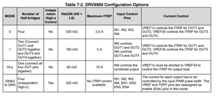
- Parallel mode- use 1 input to control IN2, then use 2nd pin to control the sleep mode to stop supplying power to TEC.
-
-
- is this recommended? Would this cause any issues with the overall health of the device?
-
-
- Mode to GND w/ 330k- use 1 input to control EN1&2, then use 2nd input along with a Not gate to provide opposite inputs to IN1&2
-
-
- Is this recommended?
-
- Would an issue arise if an input signal is applied to the device before or during the Twake Time?
Thank you for your time!
(edit: removed excessive bullet points)