This thread has been locked.

If you have a related question, please click the "Ask a related question" button in the top right corner. The newly created question will be automatically linked to this question.

BOOSTXL-DRV8320S: Sensorless motor control issue with 1xPWM

Part Number: BOOSTXL-DRV8320S
Other Parts Discussed in Thread: MCT8316A, DRV8320

Hi,

I want to control the BLDC motor I use in my project without a HALL sensor. For this, when I looked at the datasheet, I produced the HALL signals myself and the motor misfires. How can I stabilize this?

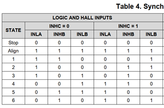
I open the outputs in the order indicated in the table above.

What am I doing wrong?

  • Hello Ali,

    Thank you for your question and posting to the MD forum. Just to clarify by the motor misfiring what do you mean exactly?

    Keep in mind that the hall outputs are generated based on the position of your motor, if you are generating the outputs from the MCU at random without any indication of the motors actual position this could be why you are seeing this "misfire". Also note that the duty cycle of your input PWM signal is what determines the speed of your motor.

    Best,

    Isaac

  • Hi Isaac,

    "Keep in mind that the hall outputs are generated based on the position of your motor, if you are generating the outputs from the MCU at random without any indication of the motors actual position this could be why you are seeing this "misfire"." This is exactly what you are talking about here, but I am giving that order according to the table above, but what should I use to understand what position the engine is in?

    If possible, can you share if you have a sample structure for 1xPWM mode and Sensorless use?

  • Hello Ali,

    I will send a reply to your question tomorrow!

    Best,

    Isaac

  • Hi Isaac,

    I'm waiting. Thanks.

  • Hello Ali,

    The 1xPWM mode on this device is not intended to be used in a sensorless method, it could be possible by monitor the BEMF of the motor to identify the position and generate the hall states with the MCU but we unfortunately do not have any sample structure for this use case.

    This would slightly be overcomplicating it since we do have the MCT8136A which can handle this use case offering trapezoidal commutation using 1xPWM for sensorless motor applications. The MCT8316A has built in FETs so this could simplify your system but unfortunately, the max voltage this device can handle is 40V compared to the DRV8320 which is capable of 65V. Not sure what the voltage rating of your motor is so hopefully this device meets those requirements.

    Here is a video on sensorless vs sensored control which you might find helpful: https://training.ti.com/ti-precision-labs-motor-drivers-sensored-vs-sensorless-control?context=1139747-1138777-1139742-1140261

    Best,

    Isaac