Hi TI Technical Support Team,
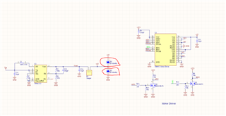
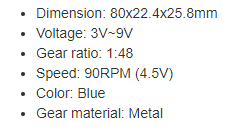
I have designed a board which have some sensors (Temperature, humidity, accelerometer etc), buzzer and motor driver IC (TB6612) on it. The power to the board is from 1S 2200mAh 18650 lithium ion battery. The battery voltage is converted to 3.3V through TPS62082 to power sensors and mcu, and to 5V using TPS61251 to power motor driver IC and buzzer circuit. The motor driver IC, TB6612, has built in back emf diodes and I am controlling 2 DC motors (3-6V 250rpm hobby dc motor) with it. Sum of the current of these DC motors under load is 500mA at max.
My concern is regarding back emf protection during manually rotating DC motors during power off or during power on. The maximum allowable voltage (maximum rating) of TPS61251 IC output pin is 7V. During power on or power off, if I manually rotate the wheel, then it will cause emf voltage and may charge Vout pin to above 5V and if this voltage exceeds 7V this will most probably damage the IC.
Do you think putting schottky clamp diodes on 5V rail (like I put in the attached file) can provide overvoltage protection against back emf? Or is it better to use TVS diodes? I read "Integrated Protection Against Back EMF Overvoltage in Motor Drive Systems" app note from TI but the IC I use does not have brake pin. I have attached schematic to this post.
Thank you in advance for your help,
-Ahmet