This thread has been locked.
If you have a related question, please click the "Ask a related question" button in the top right corner. The newly created question will be automatically linked to this question.
After troubleshooting the Eval board for way too long,
I have taken a DRV8350H-EVM and disconnected the included Microcontroller's control signals from the DRV8350 since I was getting MCU faults with no explanation
This is to try and get an even more basic dev board with the DRV8350H acting as a "dumb" motor driver.
I am trying to spin a motor with 5V hall sensors
I brought out the following signals to play with in 1X PWM mode:
I removed the 3.3V pull ups on the hall sensors ( R42, R43 and R45) and populated R46, R48 and R51
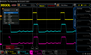
The motor can "spin" but, all phase Voltages in reference to GND are equivalent, So I believe it is just turning on and off rapidly. I Especially believe this because the motor is stuttering and not really spinning.
am not sure what i am missing
Enable and INHA work as expected. where ENABLE will start or stop the motor and the PWM signal on INHA duty cycle increases and decreases "spinning" speed.
DIR seems to do nothing, floating or pulled to 5V has the motor turn the same direction.
Below is a capture from my scope that has all 3 phases of the motor when it is "spinning"
Hi Michael,
Can you zoom in on the waveform to show if the phases all each phases are 120 degrees apart? When the FETs have the same output, it may have entered a fault condition and can be determined by monitoring the nFAULT signal. (D10)
Can you show the Hall sensor outputs from the motor? Do they have the distinct states as shown below for the direction used? Is INLC = 1 so brake is not initiated? Can you remove the pulldown capacitors from the Hall signals for smoother Hall switching?
Thanks,
Aaron
Hi Michael,
Can you double check your Hall sensor connections? This post has helped a few customers with 1x PWM mode on DRV835x recently: https://e2e.ti.com/support/motor-drivers-group/motor-drivers/f/motor-drivers-forum/845535/faq-how-to-ensure-correct-alignment-of-hall-sensors-and-your-motor?tisearch=e2e-quicksearch&keymatch=How%20to%20Ensure%20Correct%20Alignment%20of%20Hall%20Sensors%20and%20Your%20Motor
Thanks,
Aaron
All ofthe below images were taken at the following conditions
Zoom in of the phases while "spinning" (in reference to GND again)
Hall sensors while "spinning" measured at R46,48,51 (with Pulldown caps still installed), hall order looks backwards but, the motor is spinning counter clockwise compared to clockwise when I set up the halls and phases according to the FAQ you linked below)
Hall sensors without the pulldown caps installed while "spinning"
nFAULT pin while "spinning" (stays high when not spinning as well)
nBrake does not behave how you described, when I pull it high, the motor brakes, when i pull it low or leav it floating, the motor is allowed to spin.
Hey Michael,
We will review your scope captures and provide a response tomorrow. We appreciate your patience!
Best,
Isaac
Hi Michael,
Thanks for sharing the waveforms. Hall signals look fine. You are right, these phase outputs look bad. It appears the internal commutation table is not doing what is supposed to do, there should be no state whatsoever for these phase outputs turning on at the same time.
We will run the same test next week using a Function Generator, can we provide a reply by end of day on Monday?
Thanks,
Aaron
Yeah, whenever you get the chance to reply is fine. I just want to make sure I am giving the DRV8350 the best chance I can for an eval period.
Thanks Michael,
We should have results for you by the of the week. We appreciate your patience!
Best,
Isaac
Hi Michael,
Still working on this, we got 1x PWM to spin (very uncontrollably yesterday). Trying to blue wire the PWM and ENABLE signal to remove all MCU functionality.
Thanks,
Aaron
Hi Michael,
I blue wired an external PWM signal to the PWM net on the EVM. I was able to get it to spin with the following procedure, but the MOTx waveforms did not look great. This is what I did:
- Power on EVM
- Apply external PWM signal
- Power on MCU via micro USB
- Launch DRV8350 EVM GUI (I think this provides ENABLE = 1)
- Slightly spin the motor by hand to spin to start the motor spinning
- Motor changes speed according to PWM
The MCU_FAULT LED is on the majority of the time I believe due to a software fault, not the DRV835x, so the device keeps spinning. But again the output waveforms did not look great, could be a lead angle issue from the motor or hall sensors or misconfigured gate drive current.
I have a teammate working on this now to provide further updates.
Thanks,
Aaron