This thread has been locked.

If you have a related question, please click the "Ask a related question" button in the top right corner. The newly created question will be automatically linked to this question.

DRV8706S-Q1EVM: SPI communication from external device

Part Number: DRV8706S-Q1EVM
Other Parts Discussed in Thread: DRV8706-Q1

Hi, I am working with DRV9706S-Q1EVB and a 5V MCU eval board. Trying to get SPI comms working well. 

MCU Eval board SPI and GPIO is at 5V logic level. I have removed all the 0R resistors (R65 to R82) between the onboard micro and the DRV8706S. 
I have powered the DVDD pin next to R65 with 5v from the MCU eval board. I have set the nSleep to 5v from the MCU eval board. I can connected Gnd between the 2 eval boards. 

I run the SPI at 1000000 baud, CS is active low, clock is idle low, data is read on trailing edge, MSB first. 

I find that when reading from IC_CTRL the LOCK bits are not returned as I expected. In D/S it says the LOCK bits shall be 0b011 from reset which is UNLOCK. 
I try to write 0b011 to these bits but a further read does not give expected result. 

I find when I write to a register I get values returned in the 8 Data bits, although the D/S says it will be NULL values. 

Also reading from many other registers the value received does not look correct compared to the expected reset value from D/S.

I have provided PVDD power, but not connected a load or tried to drive any current / PWM out from the Hbridge. I have not tried to set the En_DRV bit in IC_CTRL. 

Just trying to read valid values from registers and write some values, for example in DRV_CTRL_1

Is there anything extra I need to know not covered (or seen by me) in the D/S, such as power up sequence, need to have load connected, correct way to use LOCK bits ? 
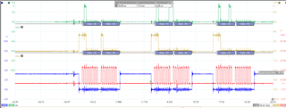
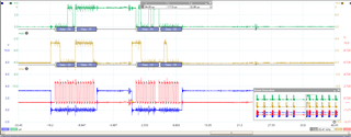
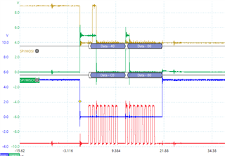
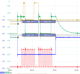
I will attach some images of scope traces. Grateful for any help. All traces are same voltage scaling 5v = 2.5 div

Blue = CS. Red = SCS. Yellow = SDI, Green = SDO

Read IC_STAT_1. Global diag values = 0xC0, data = 0x80  SPI-OK is set

Read VGS_VDS_STAT Global diag values = 0xC0, data = 0x81  SPI-OK is set

Read then write to IC_CTRL. 

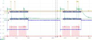
Lock bits read as 0b010 

  • Dan,

    We are looking into this.  Before you modified the EVM, did the device communicate properly with the GUI?  Just trying to rule out a device issue.  

    Regards,

    Ryan

  • Hi Ryan, 

    Yes the DRV8706 device did communicate OK with the EVB onboard MCU. 

    I took a trace of it with a logic analyser and it looked good, I was able to use the GUI, a colleague did more work with the GUI and was able to use it OK. 

    One thing to note, when I first connected the external MCU board I only removed the 4x resistors for the SPI wires, so the DRV8706 was still being powered by the EVB 3V3 supply for DVDD although the SPI CS, SCS SDI were being input at 5V logic level when DVDD was at 3V3 for some time, could this have damaged the DRV8706 ?

    Thanks Dan

  • Dan,

    I don't believe that will cause damage, but only one way to find out is to re-populate resistors and test with GUI again.  While you are at it, you can capture some waveforms and see if everything looks OK and compare to what you are seeing with external MCU.

    Regards,

    Ryan

  • Hi Ryan, 

    Thanks I will try that and let you know the outcome.

    In the meantime if you can see any problem in the traces I attached in original post or think of any other reason for this issue please let me know. 

    Thanks Dan

  • Hi Ryan, 

    I repopulated enough resistors so that the SPI DVDD and nSLEEP lines are connected to the EVB micro. 

    It is all working good using the GUI and I don't see a big difference in the traces compared to when I was trying from my micro (apart from the baud rate). I'll attach some screenshots below.  Once difference is that the evb micro seems to continue to drive its MOSI line at the same level after CS goes inactive. See second trace below. 

    One thing I notice is when doing a write to register I get the existing data back from it. But in the D/S it says the data returned is NULL. This is what made me wonder if there were other things not mentioned, or I missed, in the D/S that I need to do. 

    Blue = CS. Red = SCS. Yellow = SDO, Green = SDI

    Write to 0x06. Note that the old data 0xFE is returned not NULL data 

  • Dan,

    I have verified that this is a mistake in the datasheet!  Below, is what is should say in datasheet:

    For a write command (W0 = 0), the response word consists of the fault status indication bits followed by the existing data in the register being written to.

    So, that at least clears that up.  And it appears the DRV8706 was not damaged.  

    Regarding other issues, you mentioned the baud rate is different.  Can you take a few zoomed in measurements and ensure all the timing requirements are met per Table 6-6 in the datasheet?  That is the only thing I can think of.  State of SDI after /CS goes back high should be a "don't care". 

    Regards,

    Ryan

  • Hi Ryan, 

    we have been looking at the timing following table 6.6. the only item we are not clear on is tDIS_nSCS, other timings look to be within the spec in Table 6.6. Please see attached doc for more details and zoomed in screenshots. 

    DRV8706_Timing_Measurements-01.docx

    Another question for you. 

    When entering Sleep State from Standby State or Operating State (nSLEEP tranistions LOW to HIGH, DVDD power is present, PVDD power may be present) Are the SPI accessed control and status registers reset, or do they hold their values ready for the next transition to Standby State or Operating State ?

  • Dan,

    I think you meant to say that nSLEEP transitions from "HIGH to LOW" if you are talking about entering the sleep state.  When that happens, all the SPI registers are reset to default and it would be necessary to send SPI commands again when device exits the SLEEP state.  

    Regards,

    Ryan

  • Hi Ryan, 

    Thank you for explaining the SPI registers are all reset in SLEEP mode, and yes I meant to say nSLEEP HIGH to LOW Slight smile

    Will you have a chance to take a look at the zoomed in traces of the SPI signals where we tried to evaluate if we are within the timing requirements please.

    Also do you think there could be excessive noise or something on the wires ? I kept the wires between the boards as short as possible. 

    Another colleague has a second DRV8706S eval board now. When he monitors the SPI signals on that board with the onboard MCU communicating with the DRV8706S he gets much cleaner signals, but the baudrate is around 8x slower than on the eval board I was using. 

    Thanks Dan

  • Dan,

    Thank you for providing the plots.  The specification in question isn't even controlled by your MCU as it is the SDO output of the DRV8706-Q1, so I don't think that is an issue.

    I am having trouble understanding the voltage levels.  Have you verified that the signal is swinging between 0V and 5V as expected?  Is VDD to our driver clean?  I believe you mentioned before, but you have GND connected between the boards?  Just want to make sure there is not some sort of GND shift.

    Regards,

    Ryan

  • Hi Ryan, 

    Yes I connected GND and the 5V supply from the MCU board to GND and the DVDD pin on the DRV8706S board.
    Also connected the 5v supply to the nSLEEP pin. Yes GND was connected. 

    I will try to check if the 5V at DVDD is clean. 

    The SPI voltages are swinging from 0v to 5v, you can see in the original traces I posted as images at the top of this thread. 

    If you need me to post something specific from the scope traces please let me know. I could post the PicoScope data file if that helps. 

    Thanks Dan

  • Hi Dan,

    Ryan is OoO today. Please wait our feedback by tomorrow.

    regards

    Shinya Morita

  • HI Dan,

    Ryan is still OoO. I have reviewed your post and checking DVDD is good way. I understood your nSLEEP=H, it is OK. DRVOFF should be Low to start driving output. 

    Thanks,

    regards

    Shinya Morita

  • Dan,

    Did you get a chance to check DVDD?  One thing I haven't checked closely is if the number of clock pulses are correct for a read and matching the EVM.  Do any writes/reads work or just some registers return unexpected results?

    Regards,

    Ryan