This thread has been locked.

If you have a related question, please click the "Ask a related question" button in the top right corner. The newly created question will be automatically linked to this question.

DRV8832-Q1: Integrator delay and and motor speed control

Part Number: DRV8832-Q1
Other Parts Discussed in Thread: DRV8830, DRV8832,

Hello,

In a previous post there was mention that

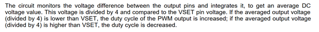
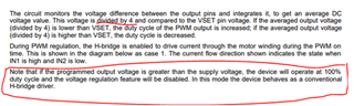
>VSET can be adjusted while the motor is running, but there will be some delay before the motor meets the new target voltage due to the integrator shown in the functional block diagram.

I am interested in using this for a robotics platform that will have an inverted pendulum task (2-wheeled balancer) and worried about any added delay. How much delay are we talking here? Microseconds? Milliseconds? Seconds?

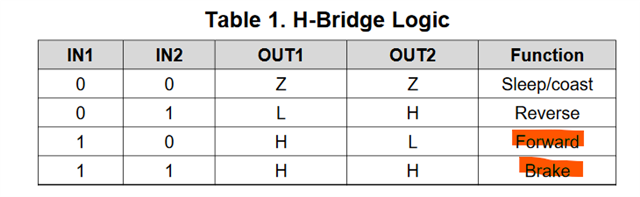
Also I am curious about how the forums and how the datasheet are specifying to control the motor speed. According to the datasheet (Section 7.3.2):

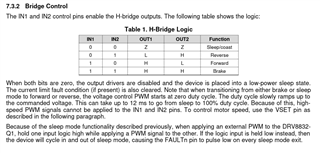
It says we should "hold one input logic high while applying a PWM signal to the other. If the logic input is held low instead, then the device will cycle in and out of sleep mode, causing the FAULTn pin to pulse low on every sleep mode exit." Wouldn't this cause the times where the PWM is low to Brake the wheel as opposed to coasting? This seems like it would generate a bunch of near-stall current. Can someone clarify if this is correct and if so, why this wouldn't cause near stall currents to be induced with each PWM cycle? If this is wrong, and we are supposed to be holding the logic input low, then how do we avoid this FAULTn?

Best regards,
Christopher

  • Hi Christopher,

    I am interested in using this for a robotics platform that will have an inverted pendulum task (2-wheeled balancer) and worried about any added delay. How much delay are we talking here? Microseconds? Milliseconds? Seconds?

    This delay will be in the range of microseconds.

    Wouldn't this cause the times where the PWM is low to Brake the wheel as opposed to coasting? This seems like it would generate a bunch of near-stall current. Can someone clarify if this is correct and if so, why this wouldn't cause near stall currents to be induced with each PWM cycle? If this is wrong, and we are supposed to be holding the logic input low, then how do we avoid this FAULTn?

    When both control signals IN1 and IN2 are LOW, the device goes to sleep mode. In sleep mode, the H-bridge is disabled (High-Z). BRAKING only occurs when both HIGH side FETs.

    This seems like it would generate a bunch of near-stall current. Can someone clarify if this is correct and if so, why this wouldn't cause near stall currents to be induced with each PWM cycle? If this is wrong, and we are supposed to be holding the logic input low, then how do we avoid this FAULTn?

    I don't really follow your question. Can you clarify.

    Regards,

    Pablo Armet

  • Thank you Pablo for your reply.

    When both control signals IN1 and IN2 are LOW, the device goes to sleep mode. In sleep mode, the H-bridge is disabled (High-Z). BRAKING only occurs when both HIGH side FETs.

    The datasheet says we should "hold one input logic high while applying a PWM signal to the other. If the logic input is held low instead, then the device will cycle in and out of sleep mode, causing the FAULTn pin to pulse low on every sleep mode exit."

    Doesn't this imply for moving forward at 50% output, we should be holding IN1 HIGH, and PWM with 50% duty cycle on IN2 according Table 1 H-Bridge Logic in the screenshot above? If so, when the PWM signal is HIGH during (50% of the cycle), this would result in IN1 HIGH and IN2 HIGH which would result in the "Brake" Function according to the same table.

    If I'm misunderstanding something here, can you please illustrate how we should apply a 50% duty cycle PWM to go forward at 50% output without braking and without causing FAULTn pin to pulse low on every PWM cycle?

  • After looking at the eval board (https://www.ti.com/lit/ug/slvu472/slvu472.pdf?ts=1654791698084)

    It looks like the speed is controlled via Vset via a variable voltage and a pot or some external voltage source. Can you use PWM to vary the voltage on Vset or how would you programmatically control the speed with DRV8832-Q1? The DRV8830 looks like this is controllable via I2C, but would think the DRV8832 has some way of controlling the speed via PWM, but maybe I have misunderstood this.

  • So reading through the datasheet more, I realize I need to control speed with VSET. It is still not clear to me whether it is acceptable to vary the voltage here with PWM or if I should be using a digital pot or something else (Maybe either works). Also this adds an additional GPIO per motor compared to the I2C version, which is fine in my case, but this leads to a related question.

    I don't see any recommended/absolute ratings for VSET. Can I set this all the way to VCC max (6.8V)? It seems suggested in Section 7.3.4 that if I were to use VREF, I could only set this to max of 5.14V. I wonder why this is and if it is ok to ignore VREF and use a voltage up to 6.8V?

    Also it seems Vout is not specified anywhere, but it seems suggested that the typical range is 0.75 to 4.5V according to Figure 2. Is this because of some voltage drop over the H-bridge fets? I.e. VCC of 6.8 drops to 4.5 V. That seems pretty high of a drop for fets.

  • Hi Christopher,

    Doesn't this imply for moving forward at 50% output, we should be holding IN1 HIGH, and PWM with 50% duty cycle on IN2 according Table 1 H-Bridge Logic in the screenshot above? If so, when the PWM signal is HIGH during (50% of the cycle), this would result in IN1 HIGH and IN2 HIGH which would result in the "Brake" Function according to the same table.

    If one IN is held high and the other PWM at any duty cycle, the H-bridge transition between BRAKE or FORWARD/REVERSE depending on the INx signal held HIGH. Your understanding is correct.

    It is still not clear to me whether it is acceptable to vary the voltage here with PWM or if I should be using a digital pot or something else (Maybe either works)

    VSET does not need to PWM to control the speed of the motor. The speed of the motor is control by INx signals. The longer the H-bridge is in either the FORWARD or REVERSE state, the higher the average current in the motor and thus the higher the motor speed. For example , in the case where IN1is held HIGH and IN2 PWM, the lower the IN2 ON time duty cycle, the longer the H-bridge will be in the FORWARD state. So the lower the duty cycle, the faster the motor will spin. VSET only set the output voltage regulation point and is not meant to me used for motor speed control. VSET will increase the duty cycle when OUTx_average_DC_voltage/4 drops below VSET. This will help maintain the same average current in the motor and maintain the same speed.


    Also it seems Vout is not specified anywhere, but it seems suggested that the typical range is 0.75 to 4.5V according to Figure 2. Is this because of some voltage drop over the H-bridge fets? I.e. VCC of 6.8 drops to 4.5 V. That seems pretty high of a drop for fets.

    The max VOUT will be equal to the supply voltage (VCC) but will be lower is VSET is set to regulate below VCC.

    I hope this answers your questions.

    Regards,

    Pablo Armet

  • Thanks Pablo for your reply, but I think I am more confused now. If you are in fact supposed to control the speed via the IN PWM signals, it would seem a constant Vset would lead to the Voltage Regulation fighting the input PWM control from what I'm understanding. Allow me to illustrate with an example:

    When describing the usage of VSET in Section 7.3.3 it states:

    >The circuit monitors the voltage difference between the output pins and integrates it, to get an average DC voltage value. This voltage is divided by 4 and compared to the VSET pin voltage. If the averaged output voltage (divided by 4) is lower than VSET, the duty cycle of the PWM output is increased; if the averaged output voltage (divided by 4) is higher than VSET, the duty cycle is decreased.

    If I use the example values given in Section 8.2.2.1, I have VCC varying from 4.5 to 5.5, and use Vset of 4.5/4 = 1.125V, so if the voltage between output pints (voltage over the motor) is lower than 4.5V, the regulator will increase the output duty cycle to bring the voltage over the motor back to 4.5V, and if it is higher than 4.5V, it will decrease the duty cycle.

    If I hold IN1 HIGH and PWM on IN2, at 100% duty cycle, I should be at IN1=1, IN2=1 (i.e. brake) and 0% duty cycle IN1=1, IN2=0 (full speed forward). Any PWM duty cycle at IN2 other than what would result in an average of 4.5 V over the outputs, would be adjusted by the Voltage Regulator, making speed control via the IN2 pin impossible unless you disable the Voltage Regulator by setting Vset above VCC as described at the end of Section 7.3.3:

    >Note that if the programmed output voltage is greater than the supply voltage, the device will operate at 100% duty cycle and the voltage regulation feature will be disabled. In this mode the device behaves as a conventional H-bridge driver.

    Or have I misunderstood something here?

    It also seems the datasheet and eval guide conflict with your answer, so can you please clarify?

    VSET does not need to PWM to control the speed of the motor. The speed of the motor is control by INx signals.

    This seems in conflict with the end of the 2nd paragraph in Section 7.3.2 of the datasheet:

    >To control motor speed, use the VSET pin as described below.

    and the eval board guide Section 4.2.1 which states:

    > you can set the motor voltage (speed) by adjusting R5

    and Section 4.2.4 specifics what R5 is:

    >R5 allows for the generation and adjustment of the VSET voltage directly on the EVM

    So the guide is saying we adjust VSET via R5 in order to set the motor speed. This is also what seems to be happening with the I2C interface if you look at the datasheet for DRV8830 in Section 7.3.2 where instead of adjusting Vset with a pot to adjust the speed, they set it via I2C to do the same thing.  I also see no mention on driving IN1 or IN2 with PWM in the eval board guide.

    If one IN is held high and the other PWM at any duty cycle, the H-bridge transition between BRAKE or FORWARD/REVERSE depending on the INx signal held HIGH. Your understanding is correct.

    And this isn't a problem? Maybe the term "brake" is a misnomer here? I would think this is equivalent to alternating between full speed forward (PWM high) and slamming on the brakes (PWM low). Seems like this would generate a LOT of unwanted current, and waste a bunch of power compared to cycling between Forward and Coast. I see some discussion on this in other [threads] but I'm still not quite clear on why this is. Does TI or other have an application note regarding this? At first glance it would seem applying "brake" would induce a near stall-current, but I guess I am misunderstanding this.

  • Hi Christopher,

    Thank you for the detailed information. Please give me 24 hours to review and provide an answer. Thank you in advance for your patience.

    Regards,

    Pablo Armet

  • Hi Christopher,

    Apologies for late reply.

    Also apologies for the confusion here. I was mistaken in my previous reply. You are correct, VSET can be used to set motor speed by means of voltage regulation. However, you can still use the IN1 and IN2 signals for motor speed control but the voltage regulation must be disabled first.

    Seems like this would generate a LOT of unwanted current, and waste a bunch of power compared to cycling between Forward and Coast. I see some discussion on this in other [threads] but I'm still not quite clear on why this is. Does TI or other have an application note regarding this?

    We have this app-note going over the different decay modes. The terminology for Braking is different in this appnote. The appnote refers to braking as slow decay.

    Regards,

    Pablo Armet

  • Thanks for confirming Pablo. I'll have a read through the appnote and let you know if I have any followup questions later.

    You are correct, VSET can be used to set motor speed by means of voltage regulation.

    Do you know if it is ok to control this via PWM, or do I need a steady voltage from a digital potentiometer or otherwise linear regulator? It would be easier/cheaper to implement with PWM, but I wasn't sure if there is some sampling frequency or the like on VSET that would get confused by PWM.

    However, you can still use the IN1 and IN2 signals for motor speed control but the voltage regulation must be disabled first.

    Can you confirm how to disable this? I think I made a bit of an assumption when interpreting the datasheet.

    >Note that if the programmed output voltage is greater than the supply voltage, the device will operate at 100% duty cycle and the voltage regulation feature will be disabled. In this mode the device behaves as a conventional H-bridge driver.

    I assumed that setting Vset above or equal to VCC would disable it, but looking at this again it looks like it is not disabled via Vset, but only when the "output voltage is greater than the supply voltage" so even if I set Vset to VCC, if I use PWM at IN1 and IN2 to reduce the output voltage on the motor, the output voltage would fall below Vset, and the regulator would kick in again because the output voltage is lower than the supply voltage. This in turn would mean I could only use 100% PWM (i.e. can't do anything other than full speed ahead). Can you confirm the details of how to use PWM at IN1 and IN2 and disabling voltage regulation? I'd like to build functionality into the board to test using both so would like to understand better how to implement both. 

    Best regards,
    Christopher

  • Hi Christopher,

    Do you know if it is ok to control this via PWM, or do I need a steady voltage from a digital potentiometer or otherwise linear regulator? It would be easier/cheaper to implement with PWM, but I wasn't sure if there is some sampling frequency or the like on VSET that would get confused by PWM

    The main concern with PWMing VSET is the delay, as mentioned in the post you linked, due to the internal comparator. My suggestion is using an evaluation module to test if this will work in your design. My guess is that it could work if the PEM frequency is low.

    Can you confirm how to disable this? I think I made a bit of an assumption when interpreting the datasheet

    Let me research this internally. I also made this assumption as well. I'll get back to you once I have an answer.

    Regards,

    Pablo Armet

  • Let me research this internally. I also made this assumption as well. I'll get back to you once I have an answer.

    Thanks Pablo, I look forward to hearing back from you on this.

    Best regards,

    Christopher

  • No problem Christopher. Give me until Monday EOD to get back to you.

    Regards,

    Pablo Armet

  • Hi Christopher,

    Apologies for late reply here.

    Just want to provide some closure to this thread. I checked with our design team on the question on disabling voltage regulation.

    it appears to me that if the programmed output voltage (VOUT_PROG) is greater than the supply voltage, then the device operated at 100% of the (customer  programmed duty cycle), hence autonomous control of duty-cycle is lost and we can say that voltage regulation is disabled.

    Putting it mathematically, we can say that voltage regulation is disabled if -

    VOUT_PROG > VCC                                [1]

    However we can also see from the above that

    VOUT_PROG = 4*VSET                          [2]

    Hence from [1] and [2],  we can derive the condition for disabling voltage regulation as -

    VSET > VCC/4                                        [3]

    For example simply setting VSET=VCC, should do it. 

    Regards,

    Pablo Armet