This thread has been locked.

If you have a related question, please click the "Ask a related question" button in the top right corner. The newly created question will be automatically linked to this question.

DRV8332-HT: The preload voltage issue of the UCC27201A when driving a 3-phase BLDC motor

Part Number: DRV8332-HT
Other Parts Discussed in Thread: UCC27201A, UCC27201

Hi team,

Here's an issue from the customer may need your help:

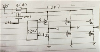
As shown in Figure 1 below, the UCC27201A drives a 24-V 3-phase BLDC motor, where the DC 24 V is controlled by controller via a PMOS switch:

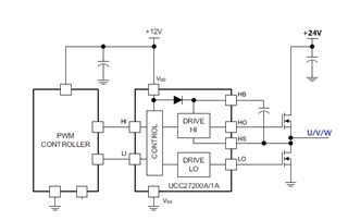
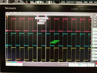
The PMOS switch has a large resistance of 3K in parallel with the D/S, and the drive waveform of U/V/W when the motor is not operating is shown in Figure 2 below. At this point, the switch PMOS is turned off, and the U/V/W drive voltage is only about 13 V after all the 3K resistor divider in parallel with the PMOS.

The U/V/W drive waveform with PMOS off and motor not operating is as follows: 

What are the benefits of this design? Why pre-add U/V/W in-phase weak voltage drive when the motor is not operating?

Could you help check this case? Thanks.

Best Regards,

Cherry

  • Hi Cherry,

    Is the customer wondering why the outputs are switching when they are not driving the motor? If so, could the customer probe the input waveforms to ensure that they are not unintentionally applying input commands to the half bridge drivers? 

    Regards,

    Anthony Lodi

  • hi Anthony,

    Actually, I have checked the input signals of Driver UCC27201, and ofcourse they are;

    what I want to know is why the designer  place the resistance of 3K in parallel with the D/S , and set synchronous U/V/W signals while turning off the PMOS period ?

    thanks for yours answer~

  • Hi Anthony Lodi,

    Thanks for your support and Copper is the customer I mentioned, you could discuss on this issue together and if you need any assistance please let me know.

    Thanks and regards,

    Cherry

  • Hi Cooper,

    I am not sure the purpose of the 3k resistor placed in parallel with the PMOS, as well as the purpose of the syncronous U/V/W signals while the PMOS is off. Do you know who designed the board? Is the synchronous U/V/W signals occurring while braking the motor? I could see a situation where all the high side MOSFETs are switched on and then after some time the high side MOSFETs are switched off and all the low side MOSFETs are switched on to allow the current in the motor to circulate and decay through the high side MOSFETs and then alternately through the low side MOSFETs in order to brake the motor. 

    Regards,

    Anthony Lodi