This thread has been locked.

If you have a related question, please click the "Ask a related question" button in the top right corner. The newly created question will be automatically linked to this question.

DRV8424E: Parallel DC Motor Operation

Part Number: DRV8424E
Other Parts Discussed in Thread: DRV8256

Can both pairs of channels on the DRV8424E or DRV8424P be run in parallel to up the amperage to 5A? If not, is there an upper limit to the parallel current operation?

Looking for maybe 3.1-3.8A reliably, but want to see how high it can go.

  • Nicholas,

    For parallel operation, please consider the DRV8256E/P.

    https://www.ti.com/product/DRV8256

    Regards,

    Ryan

  • I see that there are higher current options available with approximately the same footprint, but I'm working with an existing PCB that I may not have time to order additional parts. Is the original part able to be paralleled?

    Also, is the part you are suggesting able to parallel its outputs as well? The datasheet doesn't seem to make any mention of it.

  • Nicholas,

    No, we can't recommend this.  Due to timing variations between the two channels, a direct shoot thru from power to GND can occur when outputs switch.

    For DRV82xx parts, part is designed to drive a single H-bridge.  These outputs can't be paralleled either.

    Regards,

    Ryan

  • OK that makes more sense. However, we would be using it in a single-directional pump motor (can't run backwards, so no reason to ever toggle the PH pin).

    Would it be possible, then, to parallel them if we did not switch the H-bridge polarity? Or, more specifically, is the direct shoot-through the only reason as to why the H-bridges cannot be paralleled?

    I realize this is NOT recommended by TI at all, but I'm trying to narrow down exactly why.

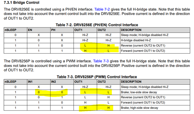
  • For the PH/EN parts, the outputs are always opposing on DRV8256 per truth table unless in HIZ state.  For PWM parts, you can configure so both outputs are HIGH or LOW.  The problem is, internally the device has different delays between OUT1 and OUT2.  As outputs are switching to that state, a shoot-thru can happen when one output is still HIGH while other is LOW.

    Regards,

    Ryan

  • Thanks for breaking it down a bit further, what I'm referring to is keeping PH = 0 and only toggling the EN from 0->1->0 so that the output only transitions from Hi-Z to L. So for example,

    • AOUT1 and BOUT1 tied together
    • AOUT2 and BOUT2 tied together
    • APH and BPH = 0, always
    • AEN and BEN can toggle either independently or together

    Then,

    • AOUT1 is then either Hi-Z or L
    • BOUT1 is then either Hi-Z or L
    • AOUT2 is then either Hi-Z or H
    • BOUT2 is then either Hi-Z or H

    In any state for this setup, there should be no possibility of shoot-through. Does that make sense?

  • Thank you for the clear explanation from your side!

    That should actually be OK.  I can't right now see a problem with it.

    Regards,

    Ryan

  • OK great. That simplifies things quite a bit on our end.