This thread has been locked.

If you have a related question, please click the "Ask a related question" button in the top right corner. The newly created question will be automatically linked to this question.

DRV8837: Internal structure

Part Number: DRV8837

Hi team,

Here's an issue from the customer may need your help:

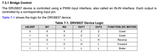
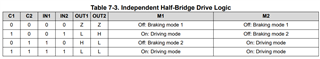
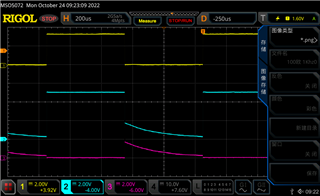
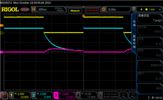
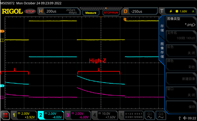
During the test, the motor was replaced with a resistive load. When the input PWM was low, the OUT1 and OUT2 voltages could not be attributed to 0 V.

For example, when VM input 5 V, everything is normal with motor; PWM is low for IN1 with resistive load, OUT1=2V and OUT2=3V. The customer wonders if this is due to the internal structure. Thanks.

Best Regards,

Cherry

  • Hey Cherry,

    Were both IN1 and IN2 low, or just IN1?  If it was both low then OUT1 and OUT2 should both be Hi-Z (high impedance), and the voltage measured could be related to any other capacitors present in the circuit that aren't discharged.  

    It should work the same with a resistive load vs a motor.  What resistance did you use?  We typically use 4Ω resistors for our resistive load tests.

    Cheers,

    Jacob

  • Hey Jacob,

    Thanks for your support.

    What resistance did you use? 

    Common lead resistance is used.

    The following waveform is PWM for IN1 in yellow, IN2 is low all the way (so no waveform is captured), OUT1 in light blue and OUT2 in purple:

    Below is the waveform with a 100 ohm load at the 100 kHz PWM wave input:

    Below is the waveform with a 1-MΩ load at the input of the 100-kHz PWM wave:

    It does seem that some capacitance is present at the output. Because PWM is low, the upper and lower moos are high, and there is no discharge of charge, the voltage is generated, and the voltage drops a little faster for low resistive loads.

    If the above understanding is correct, then decreasing the PWM wave frequency should result in a different waveform.

    Below is the waveform with a 100 ohm load at the input of a 1 kHz PWM wave: 

    Below is the waveform with a 1-MΩ load at the input of a 1-kHz PWM wave:

    From the above waveforms, at low frequencies, the waveform is maintained for a longer period of time, and a curve similar to a capacitive discharge can be clearly seen (it is true that there is capacitance in the output loop).

    However, the customer checked the peripheral circuit and did not find any capacitance. So they are wondering if there is a capacitance inside the chip?

    Thanks and regards,

    Cherry

  • Hey Cherry,

    Give me another day to look over these scope shots and address your questions.  

    Regards,

    Jacob

  • Hey Cherry,

    Thank you for the waveforms, very clear pictures with good descriptions.  

    Can you provide insight on what the goal is of this test?  Any internal capacitance of the chip should be small, but will not be zero. And a 100-ohm and 1MΩ load are very different from a <5Ω motor resistance.   Was this test run after seeing some issue with the board when driving a motor or relay?  

    Regards,

    Jacob

  • Hey Cherry,

    The device is in Hi-Z during the time that both IN1 and IN2 are LOW, such as shown in your images:

    The output signal is effectively disconnected then - it slowly floats down to ground, then is pulled HIGH/LOW based on the next drive state. This effect is more visible at 1kHz than 100kHz because the signal floats down for more time at 1kHz.  

    You might want to look at the DRV8210 - it is a similar driver, and we have a very large quantity of them in stock.  

    Regards,

    Jacob