This thread has been locked.

If you have a related question, please click the "Ask a related question" button in the top right corner. The newly created question will be automatically linked to this question.

MCT8316Z-Q1: Hall sensor placement 0° vs 30°

Part Number: MCT8316Z-Q1
Other Parts Discussed in Thread: MCT8316Z

Hi,

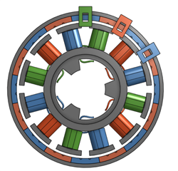
Long story short, I got a working prototype of a PCB using the MCT8316Z driver IC, with onboard motor coil and hall sensors, however I am slightly confused about which hall sensor placement are optimal. 

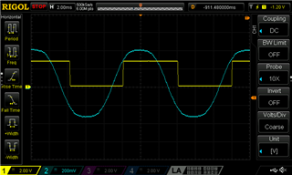
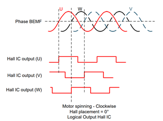
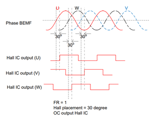
I have placed the hall sensors with a 30° phase difference between hall signal and BEMF as shown on this figure:

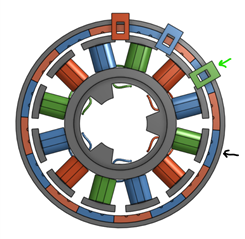
Many motor manufacturers use a 30° timing offset (why I chose it), however as this is the absolute max limit of the ADVANCE angle setting in MCT8316 I wonder if it would be better with a 0° phase difference:

Is there any difference in terms of performance or power consumption? Is there a recommended design by TI? 

Kind regards,

Emil Jacobsen

  • Hi Emil, 

    Thanks for posting your question to the e2e motor drivers forum - 

    I've assigned this thread to a team member and we'll aim to provide a response next week 

    Best Regards, 
    Andrew 

  • Hi Emil,

    Thanks for the detailed explanation. I would say there won't be any performance difference between 0 deg and 30 deg Hall placement. If the Halls are placed 30 deg and ADV angle is configured accordingly, you will not see any issues in motor performance or power consumption. 

    Regards,

    Vishnu

  • Many motor manufacturers use a 30° timing offset

    I'm not sure this is true. All motors I had worked with have the Hall signals aligned to 0 deg to the BEMF sinusoidal phase waveform. Maybe for some high speed applications that the Hall sensors were placed at 30* advanced. The amount of timing advance depends on the motor speed (phase lag). Since the 8316Z provides a selectable advance angle up to 30*, I would place the Hall sensors at 0* advance, then you can test the motor driving a load at a particular speed to optimize the advance timing (varying the Advance angle for a minimum motor current). If you layout the board with Hall sensors placed at 30* advanced, then this maybe too much and you have no way to reduce it.

    Is there any difference in terms of performance or power consumption?

    Sure there is gain in power consumption and more efficiency when the motor is commutated at the proper timing. You can set the motor speed fixed at certain rpm (closed loop controlled), then adjust the Hall advance angle and see the total motor current drops to the lowest value at a particular advanced angle. Or for open-loop with a variable input supply, when adjusting the timing advance, you can see the motor speed increases, then you can reduce the supply voltage for a desired motor speed, i.e with 0* it needs 12v for 500 rpm, but with 10* advanced it need only 8v for the same 500 rpm speed.

    Brian

  • Hi Brian, thanks for the reply. The motor I used for reference is designed with a 30° timing offset. The reason for this I believe is due to the motor winding count (12) and magnet pole pair count (16 magnets, 8 pole pairs). With this configuration, you cannot get 0° timing if you want to place normal hall sensors (South Pole towards IC = HIGH output) between stator windings.

    This is how the motor I used for reference is configured (red = A, blue = B, green = C):

    I used the same configuration in my setup, but space 120° mechanical degrees apart. As you can see, when hall sensor C (green) is right above a south facing pole, then phase C (green windings) are not aligned with a north phasing magnet. Here is a scope of BEMF and hall signal of phase C.

    Now, no matter how I place the hall sensors, I cannot get the timing offset to 0°. However, what I can get is a timing offset of 180°, by placing the hall sensors like below. Hall sensor C is right above a south facing magnet and phase C is aligned with a south phasing magnet:  

    I think I can use this placement to get a 0° offset if I instead use an inverted hall sensor (North Pole toward IC = Output High), such that the timing offset of 180° is converted to 0°. Do you agree on this? 

  • The motor I used for reference is designed with a 30° timing offset. The reason for this I believe is due to the motor winding count (12) and magnet pole pair count (16 magnets, 8 pole pairs).

    Hi Emil,

    I think you have it backward: 12 magnets or 6 pole pairs and 16 coils on the stator.

    Oops, unless you have an inside-out motor with the rotor outside the stator!!!

    With this configuration, you cannot get 0° timing if you want to place normal hall sensors (South Pole towards IC = HIGH output) between stator windings.

    Imagine the 3 sensors are mounted on the circular pcb, and if you have the sensor signals at 30 electrical advanced relative to the BEMF, then of course it is just easy to have the pcb rotated 5* mechanical toward the rotor rotating direction. Why not?

    360/6 = 60* mechanical/electrical cycle (6 magnet pole pairs give 6 electrical cycles per motor turn)

    So 30* electrical offset = 5* mechanical.

    The motor I used for reference is designed with a 30° timing offset.

    It seems to be a special custom design motor. All standard motors should have the Hall sensors to be zero offset (zero timing advanced or retarded). Why? If a motor with sensor signals at 30* advanced for CW rotation, then when it runs CCW it will then have 30* retarded and will cause overheat due to low efficiency. This is why most motors are with 0* offset Hall sensors.

    I used the same configuration in my setup, but space 120° mechanical degrees apart. As you can see, when hall sensor C (green) is right above a south facing pole, then phase C (green windings) are not aligned with a north phasing magnet.

    You can place sensor C anywhere on the circle above the magnet ring so that it turned Hi when phase C wiring is directly aligned to the North magnet.

    1. Re to the scope waveform, rotor rotating CW? If it is, then why don't you shift the sensor CCW relative to the stator such as when the green coil aligned with the N pole, then then green sensor aligned with the S pole? The sensor can be located any where on the stator, so I don't understand your limitation. 

    Regards

    Brian

  • Thanks Brian for chiming in. Emil, let me know if you need further clarification.

    Regards,

    Vishnu

  • Hi Emil, 

    Closing this thread - please let us know if you need further assistance. Thanks! 
    Andrew