This thread has been locked.

If you have a related question, please click the "Ask a related question" button in the top right corner. The newly created question will be automatically linked to this question.

DRV8251A: Question about OCP and voltage test.

Part Number: DRV8251A
Other Parts Discussed in Thread: DRV8251

Hi Team,

My customer is testing the DRV8251A and we have some question below, 

1.Customers are conducting reliability tests on DRV8251. They increase the VM to about 52V and find that the chip can still work normally. Customer wants to know how our 50V absolute maximum is tested.

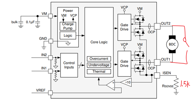
2.The customer is testing the function of OCP, using the EVM board for testing, the simple diagram is shown in the figure below.

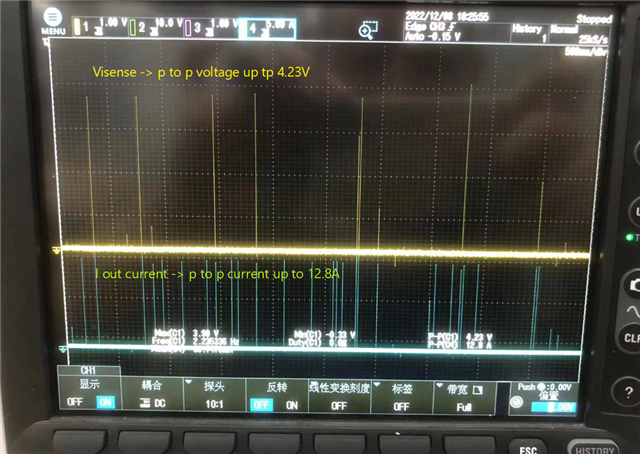
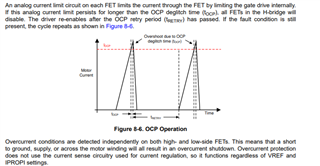
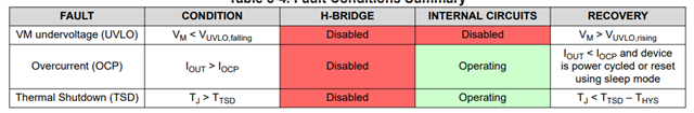
After the customer short-circuits OUT1 and OUT2 (the switch is closed), no action is taken. IN1, IN2 have PWM signal. We can see that after the current rises, it is quickly protected, and the current drops to 0. But I am very confused about why there are repeated protections. According to my understanding, after the OCP is triggered, the H-bridge should be locked, and it will be reset only when the power is turned on again. But from the waveform point of view, there is self-recovery. Do you have any comments on this? Is it possible that the OTSD was triggered first.

Thank you in advance for your support.

Jenson

  • Hi Jenson,

    1.Customers are conducting reliability tests on DRV8251. They increase the VM to about 52V and find that the chip can still work normally. Customer wants to know how our 50V absolute maximum is tested.

    The 50V specification is the maximum voltage that we can guarantee that the devices will operate as expected. The device may operate normally at voltages above 50V but we do not guarantee that it will always work.

    But from the waveform point of view, there is self-recovery. Do you have any comments on this? Is it possible that the OTSD was triggered first.

    The DRV8251A has auto-retry OCP operation which is why they are seeing the output re-enabling after some time. The DRV8251 (non-A), on the other hand, has latched OCP which requires device reset to clear the fault. I think there was a mix-up with the two datasheets. The image you posted is from the DRV8251 not the DRV8251A datasheet. The below snippet is from the DRV8251A datasheet.

    Regards,

    Pablo Armet

  • Hi Pablo,

    Thanks for your feedback here!

    One more question : If customers want to achieve Latched overcurrent protection, can they only use DRV8251? Is there a way for DRV8251A to achieve Latched overcurrent protection?

    Thanks again.

    Jenson

  •  If customers want to achieve Latched overcurrent protection, can they only use DRV8251? Is there a way for DRV8251A to achieve Latched overcurrent protection?

    No. But you can add an MCU to measure the IPROP voltage, then when MCU detect the high voltage caused by the short circuit, then the MCU software can disable the driver by control the INx inputs for zero pwm.

    Brian

  • Hi Brain,

    Thanks for your quick reply here.

    Yes, I have advised customers to use MCU for Latched over-current protection implementation. Just want to confirm if there are any will can make it through hardware. That's fine! 

    Thanks!

    Jenson

  • Brian,

    The MCU solution will be the most ideal solution. Another hardware only solution is to add an external comparator circuit with IPROPI voltage as one input and the output fed back to one of the control signals to disable the output when IPROPI is above a certain level. There is an internal 3.3V clamp on IPROPI so keep that in mind when selecting the comparator threshold level.

    Otherwise, the DRV8251 will be the better device to use if they are okay with having sense resistor.

    Regards,

    Pablo Armet

  • Hi Pablo,

    Another hardware only solution is to add an external comparator circuit with IPROPI voltage as one input and the output fed back to one of the control signals to disable the output when IPROPI is above a certain level.

    The comparator should work but the output needs to be latched with a Set-Reset Flip flop; if not, as soon as IPROPI is reduced by the OCP protection, the comparator will release the driver control input signals and this defeats the latching mechanism. 

    Brian

  • Brian,

    You bring a good point. One workaround it is to have the output of comparator to the MCU and set both control signals, or nSLEEP signal low to force the outputs to a high-Z state. The MCU can be programmed to enable the outputs after some time or when desired by user. 

    Jenson,

    Let me know if this solution will work for your application.