This thread has been locked.
If you have a related question, please click the "Ask a related question" button in the top right corner. The newly created question will be automatically linked to this question.
Hi Team
Let me ask a short qustion.
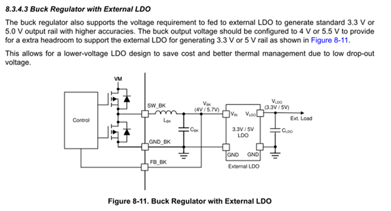
Customer want to make the circuit like below figure(Figure 8-11).
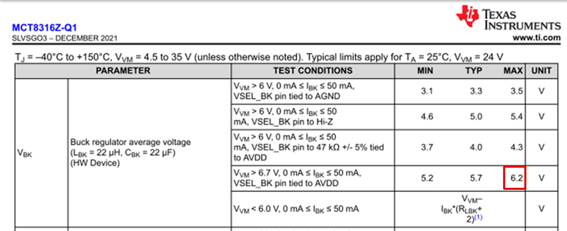
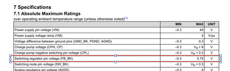
But, it seems that VBK can be 6.2V, is FB BK pin(AMR=>-0.3-5.75V) fine?
best regards
TATSU
Hi TATSU,
Thanks for your question!
Today is a holiday for TI in the US, we will aim to provide a response by the end of the week.
Regards,
Anthony
Hi Anthony
Thank you for your response.
I'm looking forward to answer .
best regards
TATSU
Hi TATSU,
I have some additional questions to better understand the customer concern. This VBK case where Abs max is 6.2V is determined by external components, is customer concerned about 6.2V being supplied to the external LDO? Can you please provide more explanation on customer concern?
The FB_BK pin in the AMR table is a known datasheet bug that will be fixed in the next revision.
Best,
Robert
Hi Robert
Thank you for your feedback.
Their concern is whether the device will not break by connecting VBK pin to FB BK pin .Not for external LDO.
best regards
TATSU
Hi Tatsu,
Thanks for the clarification.
The FB_BK pin and VBK are the same node so the FB_BK pin should be able to take the 6.2V and should not be a concern. We characterize and validate the IC at all corner cases including the 6.2V scenario. I am including a screenshot from the datasheet below that shows the circuit, hopefully this resolves your question!
Best,
Robert
Hi Robert
Thank you for your answer.
Let me confirm again, in the datasheet, AMR of FB_BK is -0.3V to 5.75V. But this is bug? True value is -0.3V to 6.2V? Is my understanding corretct?
best regards
TATSU
Hi TATSU,
Yes, you are correct.
Please help by marking this thread as resolved!
Best,
Robert