This thread has been locked.

If you have a related question, please click the "Ask a related question" button in the top right corner. The newly created question will be automatically linked to this question.

DRV8462: Driver is overheating

Part Number: DRV8462

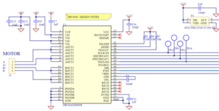
We have this driver set up with a STM uP.  We are noticing that is getting rather hot when the TI's eval board stays relatively cool.  What would be some items to look into to ensure we're set up correctly?  

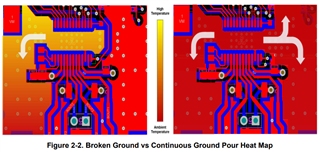
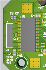
Looking at design comparisons (ours vs TI-eval) they are relatively similar.  We are going to run a thermal camera on this soon to see where heat is generating from.  I'm curious if there are particulars about this setup for our firmware and how we drive this driver.  If anyone has input or past working with this device (or in general) I would greatly appreciate it.  We're kinda scratching our heads why this is rather warm. We even added extra breakout for thermal pad (gnd) to have our heatsink apply to both the top of the device (with thermal pad) and then to the exposed square pads (with thermal grease). 

thanks. 

  • Hey Chris, 

    Can you post some pictures of each main layer on your board (top/bottom/signals), or post the Altium PCB file?  We can look through it and see if there's anything obvious that could be causing it.  

    Do you have more bulk capacitance somewhere?  I only see 10uF, you'll probably need at least 47uF and ideally 100uF (or 47uF x2) or more, preferably located relatively close to the driver.  

    Another issue could be the thermal pad layout - See 2.2 Continuous Top-Layer Thermal Pad in our Best Practices for Board Layout of Motor Drivers document.  Your PCB looks kinda similar to Figure 2-2. Broken Ground vs Continuous Ground Pour Heat Map.  I think if you could expand the GND plane for the motor driver that would improve it.  

    Did you make your boards with 1oz or 2oz copper pours?  Our boards have 2oz copper on the outside layers and 1oz on the inside.  This has a pretty big effect on current capabilities and temperatures.  

    FYI the large majority of the heat is dissipated through the PowerPad on the bottom of the device, though a heatsink on top can still help a little bit.  

    Cheers,

    Jacob

  • Thanks for the quick reply Jacob!  we ended up finding out our Vref was set differently than thought (in code).  we had it set to full scale current (5A) and comparing that to the eval board running at .5A is a difference (to say the least).  so, we're good there for now...  i will definitely take in your input to the layout tho.  so you know, the thermal pad was indeed connected (north and south) on both sides of the driver.  we do only have 1oz copper so i could see that being a difference.  we do have a 47uF cap out of view.

    but...we're having issues in reaching target velocity.  

    (this is what our firmware developer said regarding settings)

    I have full Scale current set at .5A (External Vref = 330mV)

    I have Torque DAC Setting at 100%

    Acceleration at 1000 steps/s/s

    Velocity set at 6000 steps/s

    Stalls out at 3000 Steps/s

    Do you know about setting up firmware for applying steps to the device?  if not, i would appreciate any help for getting feedback to my firmware developer so we can get this thing purring.

  • Hey Chris,

    Ahh glad you found it! That would do a lot to change it.  

    Hmm 0.5A is not very much, I recommend trying at least 1A or 2A.  If thermal is a concern I highly recommend setting up Auto Torque (see 7. Auto Torque in EVM User Guide), so the device will automatically use as much or as little torque as needed within a given range.  

    What is your microstep setting? 6000 steps/s at full step is very different output velocity from 6000 steps/s at 1/32 microstep.  Personally when I use this driver I like to set it to 1/16 or 1/32 microstep and then turn on "Auto Microstepping", so the signal output to the stepper motor is a smooth quiet sin wave but you don't have to send input STEP signals as quickly.  

    Regards,

    Jacob

  • thanks buddy.  

    i cant speak for the developer (i'm the electrical designer on this project) but i'm not sure how we integrate the drivers 'autotorque' feature in code.  if you have experience i/we'd be interested to know.  currently we try to run full current for this nema 17 stepper (2A) and we can only reach 1k rpm before stalling.  so that's where the 3k steps comes from (=1000rpm at 200 steps/rev).  

    one thing that i do notice is a difference in "feel" comparing our motors.  we have a custom LIN Engineering motor that's rated 2A at 124oz-in that we're not able to go higher than 1k rpm...then we take a Schneider/Novanta motor out of a smart motor package (70 oz-in) and it purrs like a kitten at 2k rpm.  am wondering what the tangible differences are that would make the LIN motor not as compatible with our DRV8462 setup on our pcb (not the TI eval).

    again, thanks much for the help...this is awesome collab.

  • ...and when i say "feel" i mean when spinning the motor by hand.  the schneider feels rather smooth and these LIN motors have more indexing or indents that can be felt...perhaps with a smidgeon more resistance...although it is a sealed bearing motor and so i would expect that.  but the indents are definitely noticeable..not saying that's wrong tho...just not sure.  

  • Hey Chris,

    For autotorque first follow the steps in 7. Auto Torque in EVM User Guide.  Then go to the Registers page and save/write down the values in the appropriate registers related to auto torque (see Table 7-23. Registers for auto-torque learning routine).  Then in your own code you can just write those register values and it should work if you're using the same motor.  Alternately, follow 7.3.13.1 Auto-torque Learning Routine in the datasheet.  

    Hmm and do both motors feel smooth with the EVM?  Trying to isolate whether it's something unique to your board like maybe a resistor selector, or if the register settings don't match between EVM and your board.  

    Regards,

    Jacob

  • thanks for the fb on the autotorque, i'll have conversation with the developer.  and i'm looking further into investigation of the different motors and will bring back anything notworthy.  

    if you would, list the steps you'd take to create firmware for having this driver run a motor at a step rate (choose which you'd start with) and have it capable to run 0-2000rpm.  would you utilize the additional benefits the driver offers or would you start from basics..  we're simply spinning our wheels here a bit trying to decipher why we're limited to certain speeds at certain step rates (full step being one).  i'd be curious to see your (high level) approach to tackling this.  perhaps we're limited with how we're accelerating and applicable algorithm/setup not being adequate...etc.  

    thanks again.

  • Hey Chris,

    Can you post a screenshot of the oscilloscope waveform of your motor when trying to spin it?  That can help a lot when trying to debug the issues.  Especially if you can put a current probe on one of the four wires to your stepper motor.  

    Here's a page I often refer to when trying to debug stepper motor issues: Tips and tricks for testing and debugging stepper motors

    The steps for spinning a motor at a certain speed would be broadly the same for this driver as with any other stepper motor driver with integrated indexer (STEP/DIR control with microstepping).  Typically speed limitations in a motor are due to not enough power (voltage and current) and/or too much mechanical load, or the stepper motor isn't large enough to achieve the desired speed.  

    That said, 2000 RPM is VERY fast for a stepper motor.  

    For 2000RPM at 1.8° per STEP (200 steps per revolution), 2000RPM / 60 seconds = 33.33 revolution/second, = 33.33*200 steps/revolution = 6666 Steps per second (Pulse Per Second).  This is for Full-Step, no microstepping.  If you want to run at 2000RPM and use 1/16 microstepping, then you would need to send a signal at 6666*16 = 106,656 Pulse Per Second.  

    For the DRV8462 to do this you would

    1. Set the motor driver to Awake (nSLEEP=1)
    2. Enable the outputs (ENABLE=1)
    3. Set Step Mode to desired level (let's try Full Step 100% current (Set SPI MICROSTEP_MODE to 0000b per Table 7-5. Microstepping Indexer Settings in datasheet)
    4. Set Full Scale Current (try the max value of 5A)(VREF = 3.3V typically)
    5. Set Target Speed to 6666 PPS  if using GUI 
      1. In your firmware this is where you would need to have some kind of acceleration profile to go up to 6666 PPS from 0.  You can test in the GUI what the lowest acceleration rate is that works.  
      2. Our firmware implements the acceleration profiles in a way fairly custom to our MSP430, but you can check out our firmware by downloading the software files on the EVM page.  Or you can look through the popular open-source AccelStepper library source code.  

    I also would like to point out the recent Scripting feature of the GUI that you can access by clicking Tools, Scripting Window.  Version 1.0.2 onward has scripting there, and two examples of how to use it https://dev.ti.com/gallery/view/MotorDriversBSM/DRV84xx_DRV82x2_DRV89x2-EVM-GUI/  We're still working on updating the EVM users guide to include this feature, but I think you can follow the example to get started.  This can help you set up some automation in your testing and when you change boxes that affect a register value it will put a command in the script to write to that register.  

    Regards,

    Jacob