This thread has been locked.

If you have a related question, please click the "Ask a related question" button in the top right corner. The newly created question will be automatically linked to this question.

DRV8245S-Q1LEVM: DRV8245S-Q1LEVM

Part Number: DRV8245S-Q1LEVM
Other Parts Discussed in Thread: DRV8706S-Q1EVM

Dera Team,

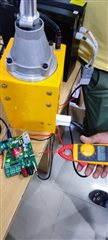
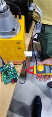
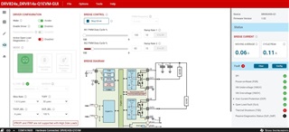
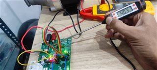
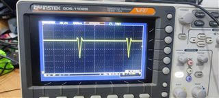
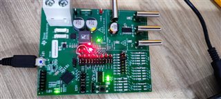
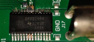
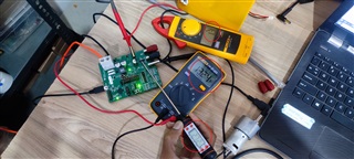
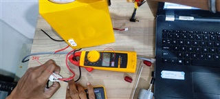
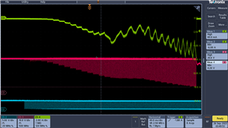
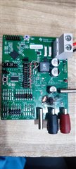
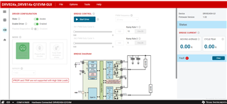
                I am working on DRV8245S-Q1 EVM now I have to connect DC high torque motor in connect as HS mode and run, as show in attached pic but when its go about to 1.2A thermal shout doun fault and DRV8245S-Q1 EVM  fault LED show. I need help to run DC high torque motor upto 20A-30A. wihe this EVM.

  • Hello Vijay,

    Is there any way you can measure the temperature of the driver? Can you capture the current and output waveforms on an oscilloscope? Are you planning on driving 20 A continuously or is that the peak current you have to handle?  This driver can only do 5.9 A continuous without PWM:

    If you do have a smaller motor that draws more than 1.2 A , can you try using that as the load and seeing if the same problem occurs?

    Best,

    Keerthi

  • Dear keerhi,

            Is there any way you can measure the temperature of the driver? -> Temp goes to 42°C

            Can you capture the current and output waveforms on an oscilloscope?-> atached output wavefom

            Are you planning on driving 20 A continuously or is that the peak current you have to handle? -> 20A is our peak current we required 4-6A continuosly

            This driver can only do 5.9 A continuous without PWM:-> yes ok for our required but at this time is not run even 1A current.

    Here one more thing is you can check attached prevouus img(DRV8245SGUI.jpg)  when I set PWM CH2 chanle 100% - 82% this will work fine after goes PWM set down falut will rise on GUI and also fault LED bellow.

  • Hello Vijay,

    1. Can you increase the slew rate and give me a picture of the output?

    2. Did you modify any connections on the EVM and if yes what did you modify?

    3. Can you disconnect the load and just run the EVM and see if the fault occurs?

    Best regards,

    Keerthi Kumanan

  • Dear Keerthi,

              Unfortulnly The Motor driver Chip DRV8245S bunt in testing. I have DRV8245H Chip and I have replaced but here problem is that the prevous chip is S serice and new one is H serices so we modifided conection as per DRV8245H haradware required now I am stuced in one issue when I insert usb to system and tryng to conncet with GUI device not geting connection. and also nFault(Image atached) led blowing. i was tried reset, sofwere update, restarted but not get any results. if you can help regarding this that will be good.


    if not, I have ordered DRV8245S this chip but this will take a time to reach me so i want to try with current solution.

    2. Did you modify any connections on the EVM and if yes what did you modify? -> No

    3. Can you disconnect the load and just run the EVM and see if the fault occurs? -> I have in-built gear motor which used for grass cutter currently cutter not in used. when cutter is used current will go around 3-4A across.

  • Hi Vijay,

    are you using the cloud-based GUI or are you using the downloaded version. If you are using the downloaded version, can you try this cloud-based GUI:

    DRV824x_DRV814x-Q1EVM-GUI (ti.com)

    Also, what VM are you providing to the EVM?

    Best regards,

    Keerthi 

  • Dear Keerthi,

    are you using the cloud-based GUI or are you using the downloaded version. If you are using the downloaded version, can you try this cloud-based GUI:-> I am using cloud based GUI same as you shared.

    Also, what VM are you providing to the EVM? -> I have 25V, 20AH Li-ion battery, I have tested with DMM on VM terminal getting 25V.

  • Hi Vijay, 

    Can you check the solder joints on the device and make sure they are fine and if it is the right orientation. 

    Best regards,

    Keerthi Kumanan

  • Dear Keerthi,

              Please check attached pic, Yes i have crossed check that orientation of chip right and soldered properly

    Can it posible to you scudule one meeting for debuging because we need to close this issue ASAP.

  • Hi Vijay,

    Just to make sure the LED is blinking and not solidly on and it is not connecting to the GUI. Is there a reason you disconnected those jumpers in the middle are disconnected. If that doesn't work can you try this sequence:

    1) USB 3) VM 4) GUI start (error) 5)VM=0V 6) VM =13V

    Best,

    Keerthi 

  • Dear Keerthi,

    We have successfully tested our EVM and confirmed that it is functioning properly. However, we are still facing a serious problem with the current supply. One more chip has been burned today due to excessive current. This chip is very sensitive and can be damaged in a matter of seconds. We need to find a solution for this issue as soon as possible and prevent further losses.

  • Hello Vijay, 

    Does the OCP fault ever occur or is the chip damaged right away? How do you know it is excessive current? Do you have any electronic loads or any other small load to make sure the driver works fine with a smaller load? Are you able to capture the current waveforms? How are you stopping the motor?

    Best,

    Keerthi 

  • Dear Keerthi,

    Does the OCP fault ever occur or is the chip damaged right away? -> Yes I have got fault when chip damged 

    How do you know it is excessive current? -> The excessive current is caused by the increase in voltage. The DC motor has a fixed resistance, so when the voltage is doubled, the current is also doubled.

    Do you have any electronic loads or any other small load to make sure the driver works fine with a smaller load? ->I have tried the 12V supply with the same DC motor (see image) and the results are: voltage is 13V, temperature is normal 19-20°C, current is 1.2A. However, when I switch to 24V, everything changes. The driver chip heats up on the same 1.2A current.

     Are you able to capture the current waveforms?-> No.

    How are you stopping the motor?-> cotrol from GUI PWM slidder.

    Bellow is a picture of a motor that can run directly on 25V DC. The current draw is only 1.6A when there is no load on the motor.

  • Hi Vijay, 

    Did you solder down the thermal pad on the IC when you switched to the hardware variant? Can you do this if you haven't already and let me know if this improves the thermal issue. 

    Best,

    Keerthi

  • Hey Vijay, 

    Sorry you've been having all these issues.  This device should have no trouble working at 24V  and 4-6A continuously.  

    Looking at your EVM, I'm a little hesitant to continue debugging with your existing EVM as it looks like it has sustained some damage either from the device overheating previously or from the repeated removing and re-soldering of the device.  We might be chasing issues down that would be solved with a new EVM.  But hopefully that isn't the case.  Thanks for adding the extra wire to fix the GUI not connecting to the EVM.  

    What slew rate have you been using? I used the Full Bridge Junction Temperature Estimator tool and found with PWM enabled the device can quickly heat up beyond Thermal Shutdown (TSD) temperature during your stall/startup condition of 20A depending on which slew rate I used.  The device still should protect itself in this situation, but would explain a motor not spinning.  Image below used 20 kHz PWM, 24V, load of 6A with spike of 20A for 0.5 seconds, and slew rate selected is 20 V/us which is middle of the device specs. When I put in 1.6V/usec like in your first image the device goes above TSD temperature almost immediately 

    voltage is 13V, temperature is normal 19-20°C, current is 1.2A. However, when I switch to 24V, everything changes. The driver chip heats up on the same 1.2A current.

    The device is running twice the power at 24V than 12V at the same current, so a slight temperature change can be expected.  12V * 1.2A = 14.4W, but 24V * 1.2A = 28.8W.

    Let me ping another team member on this device and see if he has any other ideas.  Let me know your results testing different slew rates

    Regards,

    Jacob

  • Dear Keerthi,

    Did you solder down the thermal pad on the IC when you switched to the hardware variant?  -> I understand the importance of using a thermal pad for soldering to absorb the heat. It is solderd properly.

  • Hi Jacob,

          I performed a test yesterday after replacing the damaged chip. Everything seemed fine: the temperature was normal at 33 degrees Celsius, the current was 1.4A, and the PWM decreased from 100 to 5. The output voltage was 24V and everything ran smoothly. However, suddenly the chip burned without any fault LED indication. When I increased the PWM, it was only 2-3 and the voltage was 24.5V.

    I am worried that I am doing something wrong. Could you please try the same thing on your side and see if it works? Or could you schedule a remote session with me for live testing and feedback, If you agree, I can adjust my time according to your preference.

    This is an urgent matter that needs to be resolved quickly. We have invested a lot of time and money into this project, and we have lost three chips due to defects. This is affecting my performance at work and I cannot afford any more delays.

  • Hey Vijay,

    We tested it in the lab today with a 24V 250W DC motor.  We used 24V for VM, set the GUI to Independent Half-Bridge Control with High-Side Load as shown in your screenshot.  When running this motor full speed it uses approximately 1.2A RMS, which is smaller than your motor but still a good comparison.  

    With the Slew Rate set to 1.6V/usec and the Ramp Rate set to a low number (1 or 2), I was able to get the same result as you - Thermal Shutdown (TSD). This occurs when the current exceeds 6.00A, which is a bit odd to me since the device can do 32A, I'm going to look into that. 

    Changing the Slew Rate to any other number (4V/usec, 8V/usec, etc) solved the problem - no more TSD.  Setting a higher ramp rate (acceleration) also solved the problem.  

    This matches the data in the Junction Temperature Estimator tool.  At 1.6V/us slew rate and 6A (reasonable startup current for large motor), it goes beyond TSD within ~200ms:

    Change the slew rate to 9.8V/us (8V/us in GUI), and there's no risk of TSD:

    Can you try changing your slew rate to 12V/usec - 43V/usec and let me know if that works? If no combination of slower slew rate and slower acceleration work, then I suspect your EVM is damaged.  

    Regards,

    Jacob

  • Hi Jacob,

    I performed a test with a slew rate of 50 V/µs and a VM of 24 V and these are the results:

    - Without load, the motor ran with a current of 1.2 A, a temperature of 28-30 °C, a PWM of 80%, and an output voltage of about 20 V. It worked fine with no issues.
    - With load, the motor ran with a current of 3 A, a temperature of 30-32 °C, a PWM of 81%, and an output voltage of 21 V. It also worked perfectly with no issues. However, when I sent a stop signal from the web GUI version 1.0.1, the motor driver burned and the PCB was damaged (see attached image).

    I don't know what caused this problem on the board.

    I need a new EVM. Please suggest a new variant that is better than this EVM. It should be suitable for a DC motor that runs on 15 A in continuous mode and has a peak current of 30 A.

  • Hii Jacob,

    I checked the e-store and found out that there is no return or replacement policy. I would appreciate it if you could help me with this issue.

    www.ti.com/.../returns-refunds-cancellations.html

    What acceleration (Ramp Rate) did you use? -> I used 5 as shown in the attached image value.
    To stop, I clicked on "Stop Drive".

    Now I am selected this one EVM:  DRV8706S-Q1EVM

  • Hey Vijay,

    vijay sharma said:

    What acceleration (Ramp Rate) did you use? -> I used 5 as shown in the attached image value.
    To stop, I clicked on "Stop Drive".

    Yep that is correct.  Sorry you've had these problems, hopefully the DRV8706 works better for you. 

    The DRV8145 looks better suited for your use than the DRV8245 since you are running in half-bridge configuration.  The DRV8245 is designed to run at max current in full-bridge mode. The DRV8145 is half-bridge driver so full current can be handled in half-bridge configuration, and it has a higher current rating of 46 Amps.  

    Regards,

    Jacob

  • Hii Jacob,

              Thank you for your support. I have completed the return form and received the CPR number CPR231088915. Please proceed with the necessary steps.

  • Hii Jacob,

        TI reviewed my replacement request and decline the request, please check it and do need full.

  • Hi Vijay, 

    Give me till Monday to look into this and get back to you.

    Best,

    Keerthi

  • Hi Jacob,

                  We have recently acquired the DRV8706S-Q1EVM and we are eager to complete this project with your assistance. We kindly request your guidance and support to ensure a successful outcome without any losses. We appreciate your cooperation and expertise in this matter.

  • Hello Vijay, 

    If this issue is resolved I am going to close this thread and if you encounter any issues, please post a new thread on the forum.

    Best, 

    Keerthi