This thread has been locked.

If you have a related question, please click the "Ask a related question" button in the top right corner. The newly created question will be automatically linked to this question.

DRV8462: The drive keeps blowing up, the bridges short as soon as i attach the stepper motor.

Part Number: DRV8462
Other Parts Discussed in Thread: , LM1085, DRV8461

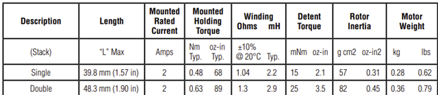
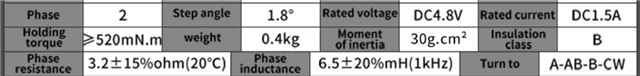
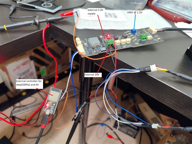
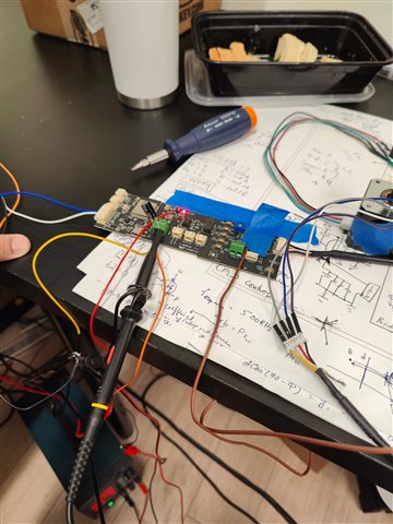
Hi I made A PCB with DRV8462, and I'm trying to control a stepper motor rated for 4A in manual mode. 

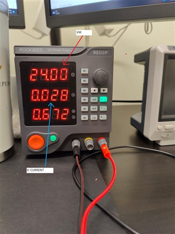
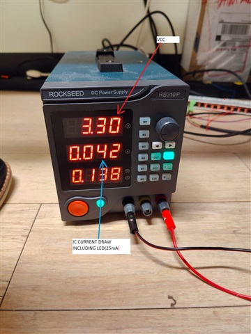
I tested the motor for 1/256 and 1/32 steps but motor wasnt responsive and drew alot of current as soon as i enable the driver, Although no step signal was given to the driver.

Then i tested the motor in full step 100% current and still the current was very high and after running for sometime the motor driver just shorted again. 

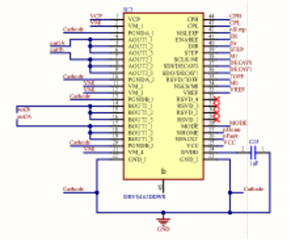
I had 4 driver ICs, and my circuit is based on the application note in the data sheet. 

The real problem is that the IC bridges keep shorting out as soon as i connected the motor. 

 The driver has a seperate layer(exposed on bottom) for heat dissipation and ground plane is not used on the IC back, the ground is given through the GND pins.

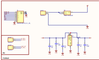
Bulk ceramic capacitors are added to the pcb, 100uF x4.  

  • Hey Ahmed,

    Can you post your schematic? 

    What is your VREF voltage? If it is 3.3V and your TRQ_DAC is max (0xFF) then the device is attempting to run at max current.  You can change either of those to lower the drive current - try TRQ_DAC of like 25% 64/255.  

     The driver has a seperate layer(exposed on bottom) for heat dissipation and ground plane is not used on the IC back, the ground is given through the GND pins.

    This is also a problem, the PowerPad is essential for dissipating device heat.  I recommend looking at 2.2 Continuous Top-Layer Thermal Pad in Best Practices for Board Layout of Motor Drivers.  Without the PowerPad attached to the ground plane I would expect the device to only be able to operate at low current levels. 

    Regards,

    Jacob

  • HI Jacob, thanks for the reply.
    here I attached the schematics for the IC. 

    https://drive.google.com/file/d/1EdH5lalABfiVpD-zxchI9FiMiUntw4J0/view?usp=sharing

    As far as the heat goes, we used a plane not connected to the ground and power pad is on that. but there is a top layer thermal pad and that goes to the dedicated layer and then exposed bottom layer all connected with vias.

  • Hey Ahmed,

    Ahh okay good, as long as the power pad has copper that should be fine then I think.  

    Thanks for the schematic, I'll review it tomorrow.  Let me know about your VREF and TRQ_DAC settings if either of those help solve it.

    Best,

    Jacob

  • All the configuration at the moment is done through H/W interface and here are the ones i tested.

    No response:
    1. Decay =  Smart tune dynamic decay
    2. Toff = 9us
    3. Micro stepping = 1/256, 1/32
    4. Vref = was set to full scale( even tried changing it)
    5.EN = auto retry mode (1)


    Some Response:
    1. Decay =  Smart tune dynamic decay/Mixed 30%
    2. Toff = 9us
    3. Micro stepping = full step 100%
    4. Vref = was set to full scale( even tried changing it)
    5.EN = auto retry mode (1)

    The circuits are made assuming that all the pins except nCS have a pull down resistor.

  • By no response, i mean this:
    1. The motor takes a jerk(very small)
    2. The current gets high rapidly and reaches the max current limit set by the power supply
    3. The motor makes high pitched noise. 
    4. Even when no step signal(grounded) is given, when the IC is enabled the coils start to draw full current. 

  • Hey Ahmed,

    Can you show your motor connections?   Is it a 4-wire motor or a 5 or 6 wire motor?  

    I highly recommend trying it out on our EVM:  DRV8462EVM That way you can isolate whether it is due to your PCB/schematic, and allow you to change settings more easily for debugging.  We've done hardware testing with very large motors - up to 65V, CNC sized motors in hardware modes, so this driver should be capable of it.  

    Please re-post the schematic, I opened it and it is very blurry like a screenshot, I can't read anything on it.  Also you should be able to attach it to this E2E post as a PDF or ZIP, our corporate policy blocks google drive links.  

    Best,

    Jacob

  • Hi Jacob, The motor is two pole, 4 wire. 

    Actually i didnt see any option of uploading a pdf directly.

    Here ive added the pdf of the schemcatics.

     New Output - PIVOT_PCB_2.pdf

  • That PDF directly worked, but is still blurry.  You'll need to export the PDF from your PCB schematic editor, I think the current PDF is just a screenshot in PDF form, or it was generated somehow with very low resolution. I  can't read any words on it to help debug. See the image below of the quality. 

    Best,

    Jacob

  • Hi Jacob sorry for that. Here is the Schematics:PIVOT_PCB_2.pdf

  • Hey Ahmed,

    Thanks for updated schematics, apologies for the delay.  I have done a review of the schematics around the DRV8462 and it all looks good. 

    What is the rate of the STEP signal you're giving?  ex. 1000 Pulse Per Second (PPS) = 1kHz?  The rate may be too fast to spin the motor at full-step

    Can you post an oscilloscope capture of the current waveform of one of the stepper motor wires?  24V and 3.3V VREF is probably too much power for a motor and would cause the "no response" you mention.

    4. Even when no step signal(grounded) is given, when the IC is enabled the coils start to draw full current. 

    FYI this is expected behavior for this stepper motor driver - whenever ENABLE pin is high the device will put the set current on the output coils.  Without a step signal this is considered holding current (applying holding torque).  STEP signal then causes the driver to advance to the next setting following the Table 7-7. Relative Current and Step Directions table.  

    Is ordering a DRV8462EVM a possibility for you?

    Regards,

    Jacob

  • Hi Jacob, thanks for your reply. Yeah the step frequency was very high in the start but i changed that to 100-200Hz for full step. 
    The motor did move for sometime, but still the current draw was alot and as i increased the current from the power supply after a very short time the IC driver blew up, Although i checked the temperature and it was not too high.

    Other thing i was concerned about is that the driver has the Over temperature protection, Over voltage and current protection but it does not kick in to save the IC.
    I dont have a problem with no response, coz i can change the parameters and try to make it work. The problem is that i had 4 PCBs made for it and all the IC just blew up in no time. That is the problem i am unable to find answer to.

    Also to change the holding current on the fly, I have to use the S/W interface?

    I have ordered the EVM to check where the issue is.  

  • Can you post a picture of some of the blown up IC's or describe what is happening - are they smoking or sparking or what? Sorry you've been having these issues.  I'm not sure why the overtemperature protection or OCP isn't protecting it. 

    Also to change the holding current on the fly, I have to use the S/W interface?

    Changing VREF accomplishes the same thing, for testing I would plop a potentiometer circuit on it and start at 0.5V or 1V and see how that works.  

    Also can you post your PCB layout or the PCB layer plots so I can review those?

    Regards,

    Jacob

  • Hi Jacob, Sorry for confusing wording. Actually this is what happens, first the IC gets shorted and the whole 24V line is clamped due to excessive current. So i take the motor off and put the power supply to a lower current level, still then the IC is shorted. I do continuity test between VM and GND of the IC and they are not shorted but when i do the test on the bridge output to the ground, they are shorted...all of them, even when the Enable is not active. 
    Another problem that occurred with some of the PCBs is that after all the above issue, my 3.3V regulator and h-bridge IC also shorted out and stopped working, Both of them were working all fine before. 

  • Hey Ahmed, thanks for the description. 

    Can you post your PCB layout or the PCB layer plots so I can review those?

    Best,

    Jacob

  • hi Jacob, thanks for your prompt reply. Im sending you the PCB files herePIVOT_PCB_2.PcbDoc

  • Hey Ahmed,

    Just to clarify the issue: When you turn on 

    Please follow the below steps to check for a solder-bridge issue across the DRV8462 pins:  Connect 24V to the board with no load connected, wake up the device, keep in Hardware mode, enable driver outputs, and you should see approximately 10mA with bridge enabled.  nFAULT should be pulled low by the driver because of Open Load Detection.  But there should be no heat, current draw should be <14mA.   Measure the current consumption with device not enabled (EN = 0) and you should get the same current. I have tested this on our EVM and am getting a current draw of 11.5mA, but our EVM has some additional circuitry. If you measure consumption of the driver significantly higher than this then there is a problem in your circuit somewhere.

    Second comment:  Please try just hardwiring the MODE pin directly to GND.  Since you're always using it in Hardware control and the device mode is read on startup, it can just be grounded.  This is just a best practice recommendation, we don't think that is the cause of the issue but will simply your design I think.  

    Is this a relay circuit?

    If you have a bare PCB without components attached, you could test with a multimeter to confirm the resistance from GND-OUTx, VM-OUTx, and between each OUTPUT (ex OUT1 to OUT2) should all measure as an open circuit.  Just to try to rule out any type of PCB manufacturing issue.  

    Best,

    Jacob

  • Thanks alot Jacob for such a detailed response. 

    Yes, Before doing any hardware settting or motor testing. I just turned on the IC and enabled it without any load. The current draw was very low and no heating issues were there. The current draw was almost the same as you mentioned. 

    Second Comment: The mode is hooked up to a switch, its not a relay. and i keep the switch in ground position. Actually my ultimate goal is to use S/W so thats why this pcb has all the option configurable through switches.

    I have a bare PCB and i will test that, this can be a good diagnostic point.

  • Hello Ahmed,

    Could you share the datasheet of the stepper motor used for the test? Specifically its DCR ohms and inductance at 1 kHz and if possible at 10 kHz. . 

    Thanks, Murugavel

  • Hi Murugavel, here are the specs of the motor

    I tested single and double stack and there was no reponse only short circuit.


    Then i tested this motor, It moved for a while but after sometime the IC shorted again.

  • Hi Jacob so I tested the continuity and also the resistance, continuity is fine and here are the resistance number:
    VM-GND = 23Kohm

    Aout1/2-GND = OL

    Bout1/2-GND = OL

    VM-Aoutx/Boutx = OL

    Aoutx-Boutx=OL

  • Hi Jacob, I noticed one thing.
    The Vm operating current is just 8mA, and in all the cases my 3.3V external regulator is also blown up. which then puts 24V on VCC and Vref which is way above than their maximum voltage levels. 
    Im still confused what could be the cause of that, and that only happens when i connect the load to the motor.

  • Hi Ahmed,

    Thanks for the information on the motors. I've run a 0.46 ohms DCR motor 3 mH and 3 ohms DCR motor 6 mH with 24V / 3A and 24V / 1.5A respectively over long periods of time with DRV8462 temperatures in the 40's C in my tests. I just wanted to rule out if anything was unusual with your motors. Doesn't look like it. The issue looks like electrical in nature. The key is current through the bridges must not increase at a very fast rate and reach FET damaging hot spot temperature inducing values before the 1.5 us current regulation blanking time expires. Also an OCP will not be detected during the initial blanking time i.e. 2.2 us in hardware mode for the DRV8462. Pure resistive shorts are known to cause such fast rising currents. Will you be able to capture the initial current including its rise time to verify if this is not happening in your driver circuit? You can use a clamp on oscilloscope current probe to look at this. 

    Were you able to monitor the temperature of the DRV8462 when you ran the second motor for a while? What was the current setting used? Perhaps the thermal pad is not properly soldered to the copper surface? Would be good to rule out these issues. If you have already done these please ignore my comments. 

    Regards, Murugavel

  • Hi Ahmed,

    What's the voltage regulator maximum input voltage specification? Does it have enough head room to safely operate at 24V? Does it have output short circuit / over current protection? 

    For further tests could you provide external 3.3V to VCC and do the tests and see if the DRV8462 still blows up when driving the stepper? Thanks.

    Regards, Murugavel

  • The regulator is fixed 3.3V 1.5A,Yes i did the test with external power supply instead of regulator.
    Here are the pictures, but still no response but the IC is not shorting now. 

    Here are the current draws: 

    VM:

    VCC:

  • I am also suspecting the current rise times, coz although the motor that worked was not working with very good efficiency but it did move for a while and the whole system only stopped working when i turned off my power supply, changed a setting(step) and turned it on.
    I don't have a current probe but ill try to measure it through some sensors that i have. 

  • Hi Ahmed,

    Names of motor output terminals look a bit strange on your diagram.

    Can you, please check with an ohmmeter (board should be unpowered) if motor coils are properly connected (not crossed) to DRV8462 IC pins?

    Regards,

    Grzegorz

  • Hi Ahmed,

    Thanks for the update. I'm glad you have isolated the 3.3V regulator failure. Perhaps the specification of the regulator were not up to the task with 24V input\. Technically with 3.3V you won't need 1.5 A. It may not exceed 50 or 60 mA including LEDs like you have indicated in the power supply current reading.

    Like Grzegorz mentioned it would be good to ensure the stepper connections were not crossed. An ohmmeter check will help verify this and also would be a good idea to mark the motor wires A1 & A2 and B1 & B2 after verification with ohmmeter at the PCB connection end. 

    Regards, Murugavel

  • Yeah, the motor wiring is pretty confusing. 
    I did check through ohmmeter also, The coil pairs are now connected in the right order.
    The wiring pairs are as follows:
    A-C  = A1-A2 
    B-D =  B1-B2

  • Hi Ahmed,

    What is the motor response with this coil pairs connections? What is the VREF voltage input? Can you share the current waveforms with us?

    Regards, Murugavel

  • The Vref voltage is 1.5V @ 3.3V VCC.
    I am now testing with EVM and the motor seems to work perfect. 
    But i am noticing the motor heating up when i increase the full-scale current.

  • Hi Ahmed,

    Thanks for the update. Good to know the motor is driven correctly now. It is normal for the stepper motor to heat up with higher IFS current setting. The heat is generated by the I2R losses in the motor windings. Typically steppers are rated for this operation. Please consult with the stepper vendor or its datasheet for maximum operating temperature and continuous rated IFS.

    Regards, Murugavel

  • Hi Ahmed,

    It is good to hear your pcb started to work. When I was checking the pcb layout I noticed that in the central part of the board there is a circuit that looks like to be operated at line voltage (230 or 110VAC for example). If it is true and MCU/Stepper motor part is to be isolated from AC part then distances (creepage) between AC part and MCU/Stepper motor part look very small on top and bottom layers. FR-4 layer 0,12-0,22 thick between outer and inner layers may not be sufficient for safety reasons as well.

    If intended use of the board is different, please ignore my comment.

    Regards,

    Grzegorz

  • Thanks Grzegorz for your additional pointers to Ahmed.

    Hi Ahmed,

    I assume all your issues with getting the DRV8462 driver to function were resolved. Please go ahead and close this post. For future questions you're welcome to start a new thread. Thanks.

    Regards, Murugavel

  • Hi Ahmed,

    I also noticed you were using the LM1085 - 3.3 for the 3.3 V supply generation from the 24V volt. The absolute max on this device is 27 V but it is recommended for use only up to 15V input while regulating for 3.3V. This may be the reason it was blowing up and shorting 24V to 3V3 and damaging other devices including the DRV8462 on your PCB. You may want to consider a different voltage regulator that would safely operate from 24V to generate 3.3V in your application. You may be able to find a drop in regulator from TI for this PCB layout.

    Regards, Murugavel

  • Hi, In the PCB the component is changed from LM1085 to LD1086-3.3v which is rated for 30V.

  • Hi, I tested the motor EVM. I am waiting for the IC to arrive so i can test in on the PCB with external power supply of 3.3V rather than the regulator.

  • Yes, Grzegorz. The PCB has a AC part, which is very low current and the voltage is provided by an isolating transformer. Plus I didn't hook up the AC 110V to the PCB and tested the stepper motor IC.

  • Hi Ahmed,

    The LD1086 is not a TI product. We cannot comment on it. 

    Regards, Murugavel

  • Hi Murugavel, So i was looking around the regulator and checked the power supply ripple voltage.
    This might be an issue and maybe the reason why my drivers keep blowing out. which in turn can cause the regulator to fail. 
    So here is the Ripple:
    Lowest voltage: -0.68V
    Highest Voltage: +23.8V
    Time for negative pulse: 15ms

    Can this be the issue why the drivers keep blowing out, even my H-bridge driver blows up. But only after i attached the load to stepper motor driver.
    Both the drivers have an absolute maximum VM of -0.3V

    The 3.3V output from the regulator is very clean. 

  • Hi Ahmed,

    It sounds like this power supply is not up to this task. What you described, a positive peak of 23.8 V and a low value on the rail below zero, - 0.68V, with motor load, is a power supply brown out condition not a ripple. Whenever VM goes < VRST, VMUVLO reset falling, the device including the stepper indexer resets so positioning will be incorrect when this happens because the indexer would lose track of the steps moved. Does the power supply not have good reservoir capacitors on the output? Usually they're in the 1000's of uF.

    A good 24 V supply commonly has better than +/- 10 % ripple under full load current, meaning the voltage excursion could be between 26.4 V and 21.6 V. While the DRV8462 driver itself does not have specific minimum ripple requirement as long as VM stays within the recommended operating voltage range, a higher VM ripple will impact the current waveform of the stepper which in turn will affect the torque output of the motor.  

    I noticed in your schematic a sizeable amount of bulk capacitance, total of 4x 100 uF. Despite these if you are seeing a huge voltage dip on VM, the power supply is definitely not suitable for the required current delivery. Please make sure the power supply rating supports the IFS current demands of the stepper. Thus far we have assumed you had a good 24 V supply for the driver. 

    And yes if you were violating absolute maximum specifications it can likely permanently damage the driver.

    Regards, Murugavel    

  • Hi Murugravel, The Power Supply is a digital bench power supply. The rated current for the supply is 10A and this dip showed even without any load.
    Yeah, the values in the schematics is 100uf x 4, but i changed them in physical design to 470uF x 4 and thought this was enough. Although i had added a 3000uF Cap before but due to space constraints we had to remove it. 

    After adding the external capacitor to the main supply input the ripple was reduced to -0.2V and time for that pulse was in the range of 24uS. 
    I repeated the power supply test and i was getting different result with a negative voltage averaging at about -0.4V. 

    I think so youre right, that when in loading conditions if power supply touches the negative rail voltage then it might burn out the driver, and that can be a plausible reason as in one experiment when the motor worked for short time, the problem only occured once i reset the power supply.

    I am thinking of experimenting like this:
    disable the driver bridge -> put it in the sleep mode -> turn on power supply -> wait for some time so voltage can be stable -> keep the IFS through Vref to a small current -> turn on the driver -> increase the IFS though Vref gradually.

  • HI Everybody. Thanks alot for helping out. Finally i am able to run the stepper motor on the PCB. The test was done using DRV8461, as 8462 is short in the market.

    An external electrolytic cap of 330uF was added

    Current limit for 24V power supply set to 2.5A

    the regulator was replaced by a 3.3V power supply

    the Vref was set at 1.9V

    the sequence was as follows:

    keep driver in sleep and disable the bridges

    Turn on 3.3V power supply 

    take the driver out of sleep 

    Turn 24V power supply on

    enable the driver

    It is still using H/W control mode to control the motor.

    The negative spikes of -0.2V are still present at no load, but no spikes at load are present at 24V supply.

    Also i did a 10minute experiment the maximum temperature at the below rated current(0.291) was 44.1C 

    Although I'm still confused about one-thing that: I have a reverse polarity diode on the main supply connector, then why does negative ripple show up on my VM.