This thread has been locked.

If you have a related question, please click the "Ask a related question" button in the top right corner. The newly created question will be automatically linked to this question.

DRV8434SEVM: Unable to get SPI to work

Part Number: DRV8434SEVM
Other Parts Discussed in Thread: DRV8462EVM, , DRV8434S, DRV8462

Hi,
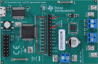
We have recently acquired a 83434, but as of yet have been unable to get SPI to work properly, in a similar setup we used on the DRV8462EVM.

Our setup is an Arduino connected to SPI of the board, with enable and nSleep connected as well and raised high, as follows:

  • SPI mode 1 and 5Mbit baud rate. We have tried other modes and other baud rates, but this one worked best on the previous stepper.
  • Setup:
    • 0x04 to 0x8F (default + EN_OUT=1)
    • 0x07 to 0x18 (EN_STL=1)
    • 0x08 to 200 - have tried many different values as well.

On the DRV8462EVM, we utilized the mode pin as well, and both pin mode (dir and step pins), and SPI step and dir via 0x05. This was successful in both setups, with various motors and various register values. In addition, on this board, SPI did not work without the board being conencted to USB as well (even though nothing is sent).

On the DRV8434SEVM, running without the USB returns nothing over SPI, while when it is connected, we consistently receive 192 on 0x00, which translates to Fault + SPI_ERROR.

What are we doing wrong? Could it be that the mode pin is incorrectly set in the board?

Thanks!
Roi

  • Hello Roi,

    Thanks for your post. When wiring the DRV8434SEVM to an external MCU for control 0 ohms jumpers of the pins controlled such as the SPI pins must be de-soldered. See below snippet. VSDO must be provided from your MCU for example 3.3 V from your MCU power supply. nFAULT may require an external pull-up resistor to the external MCU supply.. 


    The DRV8462EVM has two row headers and allow easy isolation on these pins hence the difference. SPI implementation is identical in these two devices.

    Regards, Murugavel

  • Hi Murugavel,

    Thanks very much for the swift and informative reply! 

    I have tried as you mentioned (bar the Fault pin because we use the SPI register values instead). Now I consistently receive 0's over SPI irrelevant to write what I write to the registers.

    Also I had understood that the the functionality wa that of 8434S, so I am confused as per your statement that the SPI logic is the same, since according to the data sheet, they do not have all of the same registers. Is this not the case?

    Thanks!

    Roi

  • Just to clarify hyphen, I have removed all of the resistors as per the image you sent, and not only the ones regarding the SPI communication. 

  • Hello Roi,

    Thanks for the update. By SPI logic I meant the communication protocol CLKPH and POL are the same. Yes the registers address and bit fields will be different. 

    VSDO supply connection is required for the SDO output buffer to work, this will be the logic high level output of the SDO pin. Please confirm if this was connected. Thanks.

    Regards, Murugavel

  • Hi Murugavel!

    I had connected this to 3.3 on the arduino, and the gnd to gnd on thr arduino. Was this what you meant?

    Thanks!

    Roi

  • Hi Roi,

    Yes this is what I meant.

    This device has been shipping for several years. We have not seen any issues with SPI communication with an MCU. If you happen to have a SPI decoding tool such as Saleae or an Oscilloscope can you please capture the transaction and share with us? It must follow the below shown timing protocol.

    The device must be awake for SPI transactions, nSLEEP = 1 and there is a power on / wake up delay of about a 1 ms (see datasheet) before SPI transactions can be done.

    Regards, Murugavel

  • Hi!
    It seems that the SPI level on the arduino is 5v - is this too high for the SPI logic?
    Thanks!
    Roi

  • Hi Roi,

    This shouldn't be an issue per the datasheet specifications. VSDO must be connected to 5 V in this case for 5V logic high output on SDO of the DRV8434S. 

    Regards, Murugavel

  • Still not working Disappointed

    Is it OK that I removed all of the resistors in the picture you sent, and not just the SPI ones?

  • Sorry to hear that you're still having problems. You must also remove the SPI resistors. Besides 5V on SPI pins will damage the MSP430. Also the SPI pins will be loaded by the MSP430.

  • Hi Murgavel,
    I have tried hooking up the board to a 3.3V SPI chip instead, and I am still receiving an SPI error on the fault register ( 0xC000 - meaning fault + SPI error)

  • FYI - have tried the 8462 on the 3.3V board and it works perfectly ( the connected motor moves) - however I still receive 0xC000 on 0x00

  • Hi Roi,

    Indicates SPI protocol errors, such as more SCLK pulses than are required or SCLK is absent even though nSCS is low. Becomes high in fault and the nFAULT pin is driven low. 

    It is possible such an error happening with the first transaction. For example nSCS toggled with no SPI clock pulses at startup. SPI_ERROR does not block further SPI transactions and device may work normally with further operation via SPI. If you issue a CLR_FLT via SPI the error should be cleared. If it happens again it indicates a faulty transaction again. 

    Regards, Murugavel

  • Hi,

    Indeed the motor connected to 8642 runs without issues, even with said "fault" in SPI.

    However, the same motor on 8434 does not move when SPI step is sent, with the same setup.

    Thanks!

    Roi

  • Hi,

    Does the 8434 work fine with STEP input send via the pin?

    I assume you took care of the shift in the Address bits in the DRV8434S vs. the DRV8462? See below. The address must be left shifted once for the DRV8434S. You can also perform a SPI read register and confirm if the register was written with the required bit fields. The address bit position shift applies for both read and write. 


    Regards, Murugavel

  • OK this is awkward... I had totally missed this. bit shifting the address worked of course - I get nFault consistently now, but this is a separate issue I will try to fix.
    Thanks very very much for your patience Murugavel!!!

  • Hello Roi,

    I'm glad this fixed the issue for you. No one knows what simple things I missed and debugged for hours when I used to code firmware. After the device is waken up from sleep using nSLEEP control include a delay of > t(READY) perhaps a 1.5 ms or so and then start the SPI transactions. Hopefully this will avoid the SPI_ERROR being set. Sometimes you may have to just do a one time CLR_FLT to clean things up and set up the device for the application. Thanks for the update. I'll close this thread. 

    Regards, Murugavel