Hi Team,
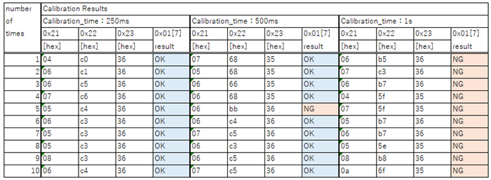
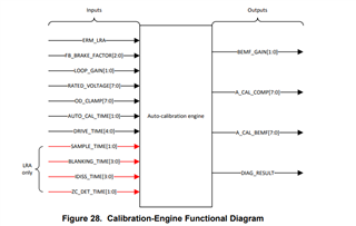
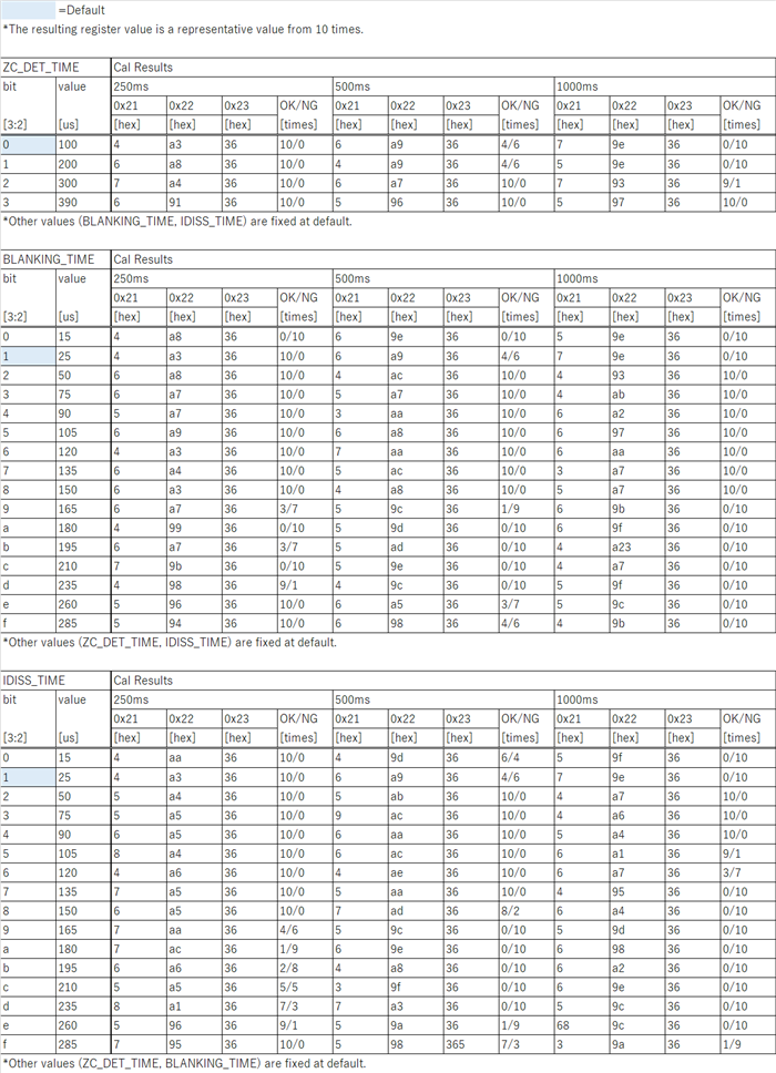
The datasheet shows that DIAG_RESULT bit is used to ensure the auto-calibration routine is complete without fails.
Could you tell me how DRV2624 determines whether "0" or "1" in auto-calibration routine?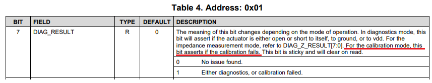
The background of the question is my customer considers to do auto-calibration procedure in manufacturing process and wants to identify the cause and consider how to fix it when DIAG_RESULT = "1" (calibration failed).
Best Regards,
Yaita

-
Ask a related question
What is a related question?A related question is a question created from another question. When the related question is created, it will be automatically linked to the original question.