This thread has been locked.

If you have a related question, please click the "Ask a related question" button in the top right corner. The newly created question will be automatically linked to this question.

DRV8243-Q1: Overcurrent limit of the driver

Part Number: DRV8243-Q1
Other Parts Discussed in Thread: DRV8243H-Q1EVM

Hi experts,

I am Anjali and this is my first hardware.

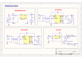
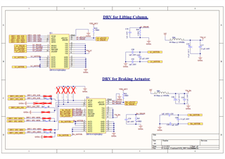
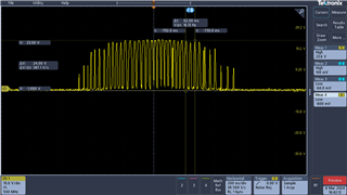
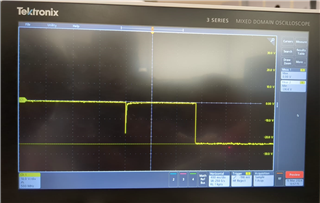
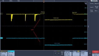
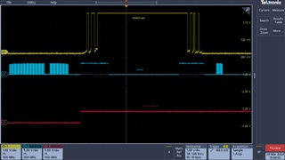
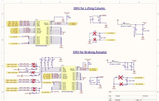
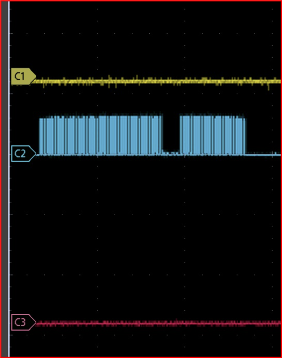
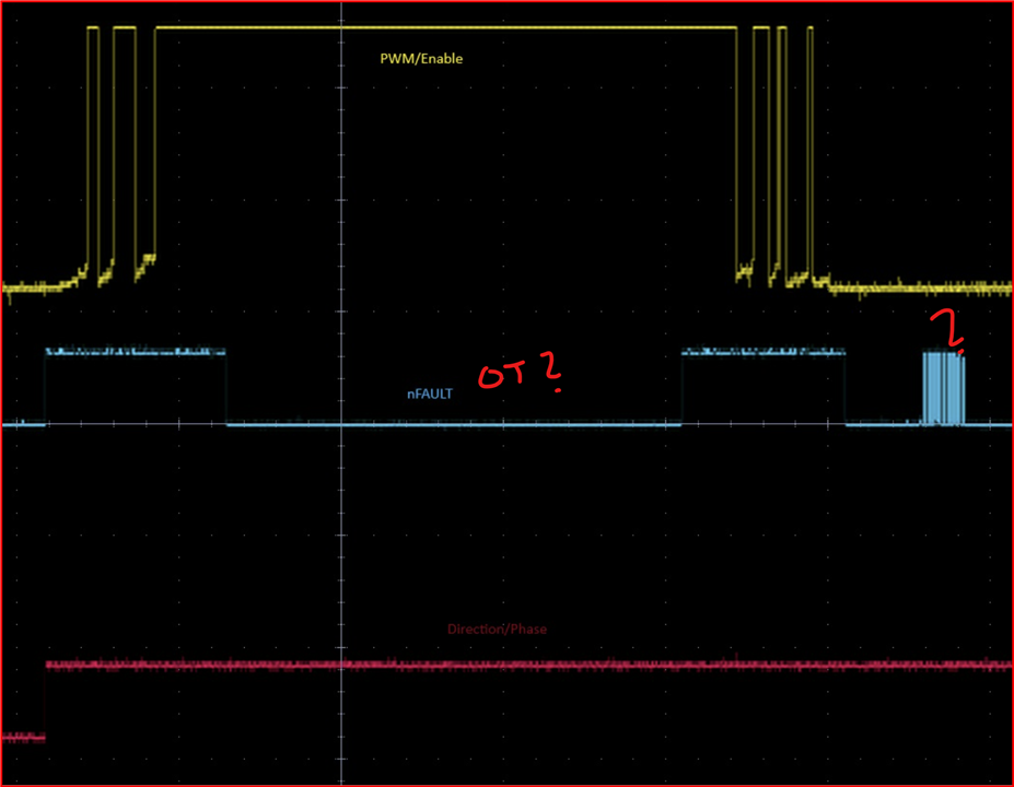
We are using the SPI version of the driver IC to drive the brushed DC motor of a lifting column. The maximum current taken by the bidirectional load is 2.2A. When testing with a different brushed DC motor (peak current drawn was 1.5A), the output was fine. However, when testing with the lifting column, the driver IC got damaged. The H-bridge is shorted causing a short between VM-GND-OUT1-OUT2. I am not able to deduce what caused the short since the driver is rated for much more than 2.2A. 

Please share your insight on this. Thank-you!

  • Hi Anjali,

    Could you please provide more details? What is the operating VM voltage of the BDC motor application? Are you using PWM to drive the motor, what PWM frequency, duty cycle and do you use a ramp up and ramp down of the duty cycle profile while start and stop of the motor? Does the lifting column operate against gravity in one direction and with gravity in the other direction or does it have a spring that could store mechanical potential energy while traveling in one direction? This may have caused VM voltage pumping that may have exceeded the absolute maximum rating of the device and permanently damaged it. This post may be of help to you to understand the potential issue, https://e2e.ti.com/blogs_/b/industrial_strength/posts/art-of-stopping-the-motor-vm-pumping.  

    Could you also describe the failure mechanism? Did it fail when the motor was started, stopped or during any other specific mechanical activity? How many devices fail? I assume this would be a custom hardware? If so could you please share the schematic as well as any waveforms of the output voltage and current you may have captured? Thanks.

    Regards, Murugavel

  • Hi,

    Thankyou for your reply.

    Operating voltage VM is 24V. We are using PWM with 50% duty cycle and 20kHz on the Enable pin to drive the motor.

    We are not using a ramp-up and ramp down of the duty cycle of PWM.

    Lifting column operates against gravity in on direction and with gravity in the other.

    Spring is not used in the lifting column. Motion in both directions is using motors. 

    We used a programmable power supply to supply 24V and set a 3A overcurrent limit. We connected the lifting column and when the board was operated, the supply kept detecting a short. The fault recovery mode was set to retry for the supply as well as the driver. About 4 seconds into testing with the lifting column, the board failed. While this was happening, the lifting column motor did not move at all. We tested twice, 2 driver ICs failed. The lifting columns were unaffected.

    We tested a different lifting column with current rating 1.5A. That lifting column worked fine with the motor driver.

    I have attached the schematic for your reference.

  • Hi Anjali,

    Thanks for further details. There may be few things on play with this application. You mentioned the actuator has a 2.2 A current specification. Would this be steady rate running current specification? Generally a BDC (brushed DC) motor has a high inrush current when started from rest until it reaches its steady state velocity. After reaching steady state velocity the current will stabilize to a lower value. This usually lasts a few ms and the peak can be > 3x to 10x. For example with this lifting column while driven against gravity the inrush will be highest. If the power supply is set to 3 A this will limit the inrush by tripping it and could result with a pulsating supply voltage if a retry is used. So technically you should avoid having a low threshold for the power supply and should not use retry setting. I also noticed a 10 uF bulk capacitor on the VM_LC power supply which may not be high enough to support the inrush current. 

    The DRV driver device over current detection can be set for either retry or latch. When the lifting column is driven against the gravity and the DRV has an overcurrent (assuming a overtemperature was not detected) this will indicate the inrush current is exceeding the overcurrent limit of this device. This can be easily verified by looking at the FAULT_SUMMARY register after a fault is reported, nFAULT = LOW. 

    Next potential issue and this may be the reason for the failure experienced. When the motor is reversed suddenly from the direction against gravity to the direction with gravity the stored mechanical potential energy momentarily would pump up the VM supply and could potentially exceed the absolute maximum rating of the DRV8243-Q1 and permanently damage the device. We have seen this happen with several BDC motor drivers. One way to mitigate this issue would be to provide a soft start and soft stop and reverse direction and then soft start. The ramp up and ramp down does not need to be very long, just enough to take care of the inertia and time taken to dissipate the potential energy is good enough. This feature is implemented in our EVM microcontroller and can be evaluated using the EVM GUI. Various ramp settings can be evaluated.

    This post also would be a good reference on this subject,  https://e2e.ti.com/blogs_/b/industrial_strength/posts/art-of-stopping-the-motor-vm-pumping. I hope this helps to mitigate this issue and prevent device damage.

    Regards, Murugavel 

  • Hi Sir,

    My apologies for the delayed response. 

    Thank-you for your response.

    2.2A is the peak current drawn by the lifting column as observed on the variable power supply. The current settles at 1.4A during steady operation against gravity. I will check the inrush current on an oscilloscope for clarity. I will also implement the soft start and soft reversal and get back to you with updates. 

    Thankyou and Warm Regards, Anjali Karmude.

  • Hi Anjali,

    Thank you for keeping us posted. One more parameter to check would be the SR setting. Be sure to use a faster SR such as 24.5 V/us or higher. Slower SR will result in over temperature with a lower peak current. The default value of SR 1.6 V/us is too slow. We will wait for your update regarding the mentioned tests outcome. 

    Regards, Murugavel

  • Hi Murugavel,

    As a you mentioned  implemented slow start and slow stop of motor using PWM, changed the capacitor at VM_LC power supply, updated to latch settings for OCP and set the slew rate to maximum. By implementing all these features first tested with the  Faulhaber Series 2642CXR we are getting the below attached motor voltage output waveforms,


    So, can you suggest whether this waveform signature is expected with the DRV8243 IC when implemented slow start and slow stop with 20khz PWM frequency and varying the duty cycle from 10% to 50%. If not please share the output motor voltage waveforms for reference.

    Thank you, Deekshitha 

  • Hi Deekshitha,

    Thanks for the update. The waveform signature is a function of the motor parameters, supply voltage and duty cycle. This would look the same regardless of the driver device used if driven with a 10% to 50% duty cycle. This looks normal. 

    What was the inrush current of the motor? 

    I assume there is no longer a over current or an IC short situation. I hope this issue is resolved with the ramp up an ramp down of the PWM. You can optimize the ramp rate to suit your application needs. In the final application the slew rate must be set for lowest switching loss as well as satisfy the EMI performance of the drive system.

    Regards, Murugavel

  • Hi Murugavel,

    Thank you for the support, now we are able to control the lifting column with DRV8243 SPI version without any short of the IC and Controller.

    Now we are trying to control the lifting column with DRV8243 Hardware version, we are facing some issues when we checked the waveform in oscilloscope.

    Here I attached the waveform when checked at the motor output terminals without any load, and i am able to get the expected voltage. But why we are getting the spike when the button is pressed and then after 1 sec the start is started. Can you please help us how to get rid of this spike.

    And to wake up the driver i have implemented the code like this, please verify and let us know is this correct implementation to wake up the hardware IC.

    nFAULT_Status1=HAL_GPIO_ReadPin(GPIOC, GPIO_PIN_8);   //BA nFAULT
    HAL_GPIO_WritePin(GPIOD, GPIO_PIN_2, 1);              //BA nSLEEP
    HAL_Delay(1);
    nFAULT_Status1=HAL_GPIO_ReadPin(GPIOC, GPIO_PIN_8);   //BA nFAULT
    HAL_Delay(0.02);
    HAL_GPIO_WritePin(GPIOD, GPIO_PIN_2, 0);              //BA nSLEEP
    nFAULT_Status1=HAL_GPIO_ReadPin(GPIOC, GPIO_PIN_8);   //BA nFAULT
       

    Thank you,Deekshitha

  • Hi Deekshitha,

    Good to know all the issues with the DRV8243S were resolved. "But why we are getting the spike when the button is pressed and then after 1 sec the start is started.". Which button was pressed? What is the EN/IN1 and PH/IN2 pins status when the spike happens? What MODE the driver is configured? Please share the schematic. the spike could be because you may not be having proper default states of the input pins for the MODE used. Anything happening 1s after startup should be something external coming in from the MCU. Check the inputs and nFAULT captures along with the spike. 

    "Now we are trying to control the lifting column with DRV8243 Hardware version, we are facing some issues when we checked the waveform in oscilloscope.". So the lifting column does not work? When you capture output waveforms please also capture both input and both output waveforms simultaneously. At the minimum the active input and active output waveform together with description of the other input and output status. 

    Regards, Murugavel

  • Hi Murugavel,

    I will let you know in the same order you have asked,

    1. In our application we are using the button for the movement of the lifting column(i.e. up button &down button). And when the button is pressed the lifting column will be moving up or down based on the direction of the motor.

    2. 

       The above waveforms are captured when the button is pressed, the motor output(Blue) and input PWM(Yellow) 


      In this waveform i captured above is PWM/Enable(yellow), nFault(blue), phase/Direction(Red)

    3. The driver is configured in Ph/En mode.

    4. Did not tried connecting to the lifting column because, we are getting the spike tried with the Faulhaber Series 2642CXR, but motor is not rotating as expected.


    Here I attached the schematics for the Hardware version.

    Thank you,Deekshitha

  • Hi Deekshitha,

    Thanks for the scope shots. 

    1. Based on the waveform the PWM from the MCU is having a spike as seen in the yellow trace. This is your firmware related issue. When the button was pressed the IO port is being written with a LOW and back to HIGH for a very short period of time or it may be from the PWM timer. This issue should be fixed. Given that this spike is very small duration it may not cause any movement with the motor. But still it is not a desirable behavior. I hope you will address this by fixing your MCU firmware.

    2. Was this scope shot captured with motor load connected? Could you describe what is the sequence? You mentioned PH/EN mode was used. In the below portion of the waveform PWM input on EN = 0 and PH = 0. Why is the nFAULT blue trace having pulses? This is not expected behavior. 

    Can you ensure the device was awaken using proper wake-up sequence as shown in page-23 of the datasheet, https://www.ti.com/lit/ds/symlink/drv8243-q1.pdf under the 7.7.2 Wake-up Transients / 7.7.2.1 HW Variant.

    In the second portion I see the EN is driven with 1 and 0, motor on and off for short periods of time with no issues. But when the EN = 1 for longer period it looks like the nFAULT shows may be an overtemperature tripping. Were you able to check the device temperature with a temperature probe or thermal camera? 

    The same nFAULT pulse behavior is seen when EN =0 in the later portion. Did you try with more than one device to rule out a device failure?

    3. Okay understood.

    4. It is likely you were exceeding the power dissipation capability of the device or the device was damaged. Did you try driving the lifting column with a DRV8243H-Q1EVM? You may have to consider the DRV8244H-Q1 or DRV8245H-Q1 if driving the lifting column motor is exceeding the power dissipation of the DRV8243H-Q1EVM.

    Regards, Murugavel